

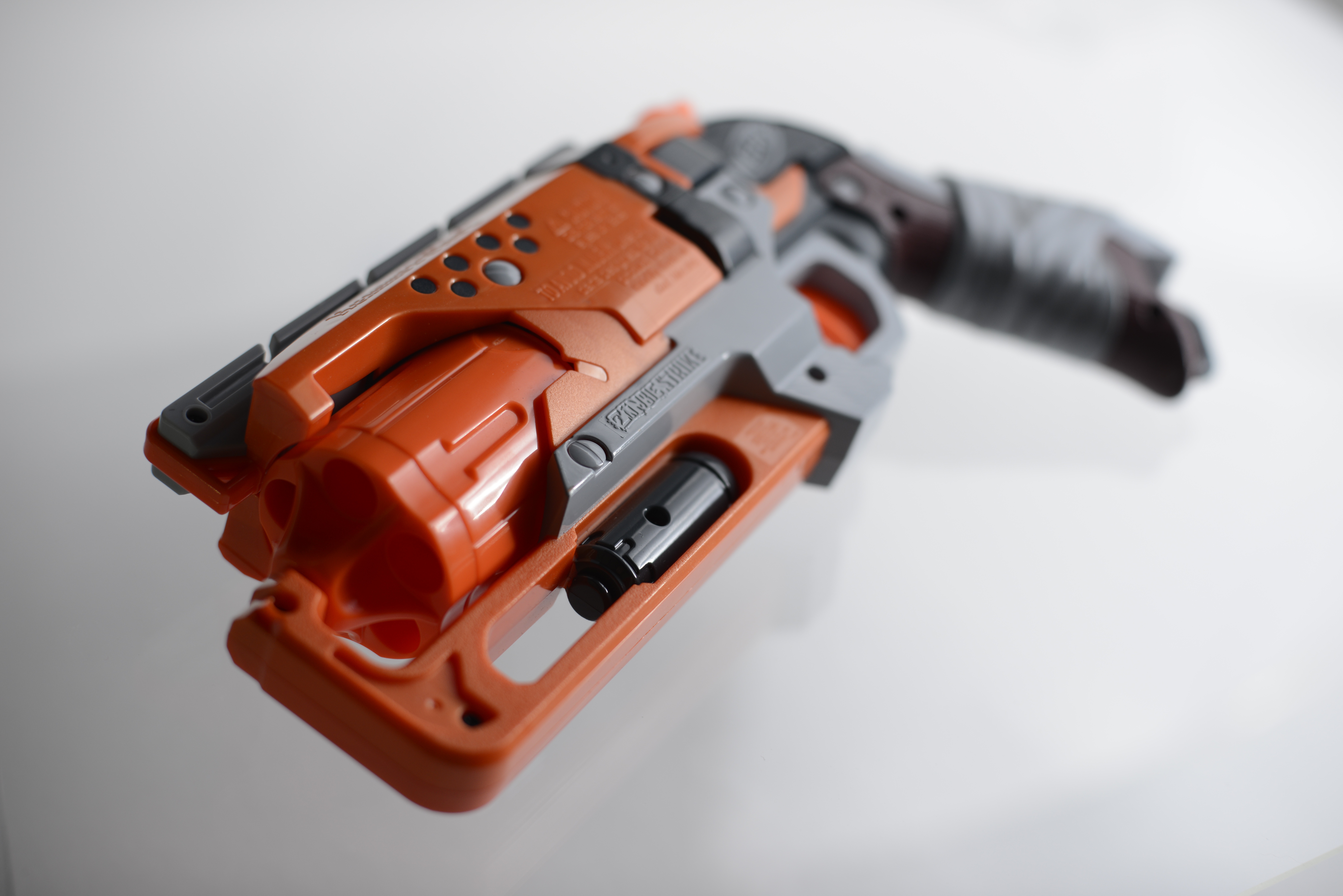
Welcome to the Hammershot's edition of The Works Guide. This guide aims to cover modifications to the Nerf Zombie Strike Hammershot. While it is not a complete guide to this relatively new blaster, it will attempt to cover several facets of direct plunger modifications as they apply to the Hammershot.
Read on after the jump...
Many of the concepts used have been previously applied and developed by the Nerf modding community. We here at Better Nerf By Science do not attempt to present them as original techniques, but as a concise and focused guide specifically designed for this blaster.
The modifications in this guide can be applied to other similar blasters, such as the Rebelle Sweet Revenge or the Dart Tag Snapfire 8. The Sweet Revenge seems to be a cosmetic makeover of the Hammershot, so modifications should apply directly. The Snapfire 8 uses a similar system, but the ideas are still valid and applicable.
Note:
Any tool that fits the listed description can be used. The first
specific item below the description is the tool used in making this
guide. Additional options may be shown.
Required:
- Small flat head screwdriver
- Stanley Jewelers Precision Screwdriver Set: amazon - Hot glue gun
- Dikes, which are diagonal or side-cutting pliers
- Hand drill or drill press
- Silicone Lubricant
Recommended:
- File or sandpaper
- Dremel
- Hot air gun
D. Parts
Note:
Any part that fits the listed description can be used. The first
specific item below the description is the part used in making this
guide. Additional options may be shown.
- Spacer for increased spring compression, use one of the following (refer to section E.8 for McMaster differentiation):
- Correct diameter spring for increased power, use one of the following (listed in terms of strength):
- 8kg SG Nerf Retaliator spring (SG Nerf ModWorks)
- 5kg OMW Retaliator spring (OMW)
- 2.5 kg stock Retaliator spring
- stock Maverick spring
-
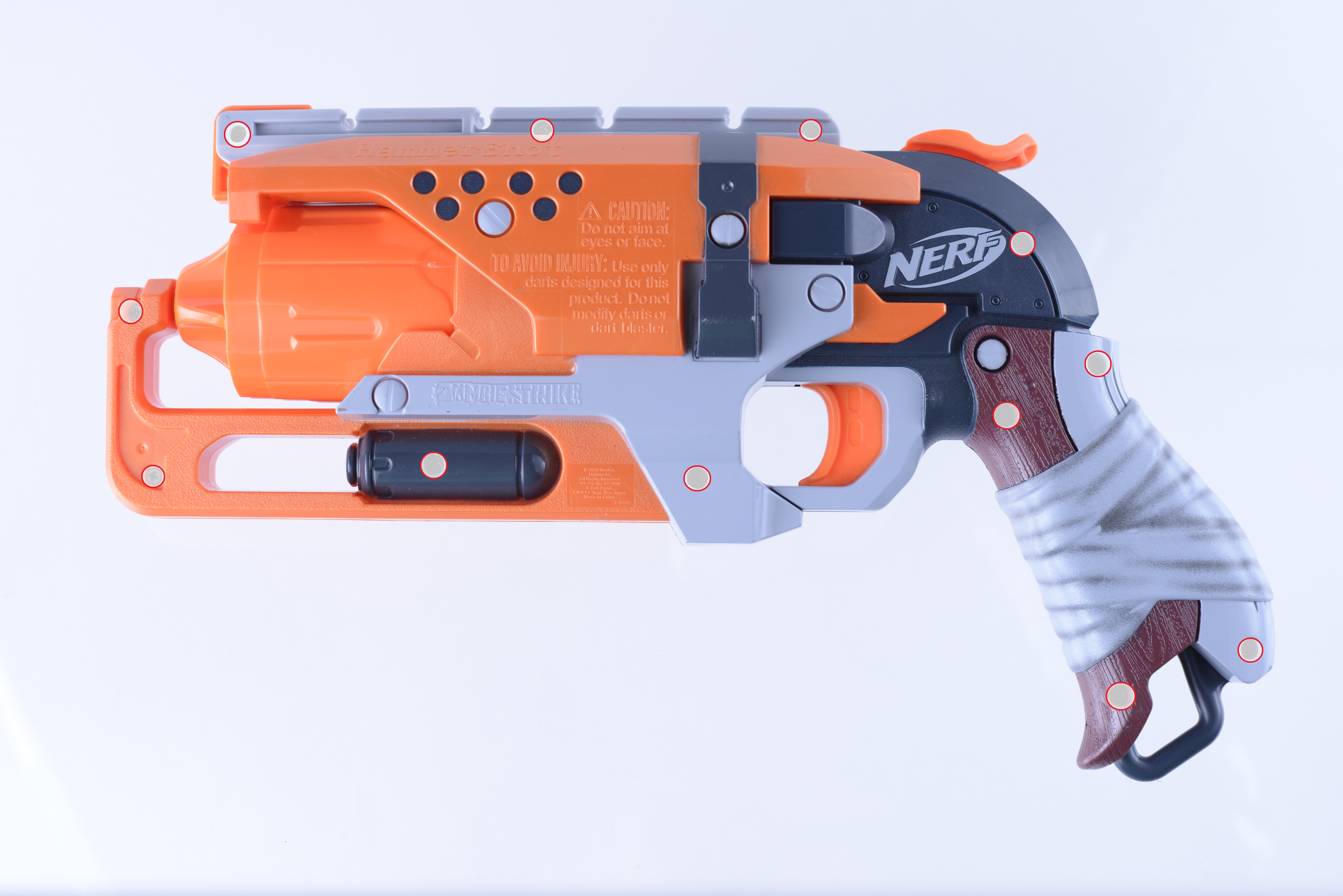
Make sure the blaster is not primed before you open the blaster. There are 12 screws, as indicated in the picture below by the red circles. They are all of uniform length and threading, which makes reassembly much easier. The tactical rail spring seems to be a bit weaker in this blaster, as it does not have the tendency to pop out. Even as such, it is recommended to either place a dab of hot glue to hold it in place, or keep it somewhere safe during modification.
Fig. E1.1 - Hammershot Screw Positions
-
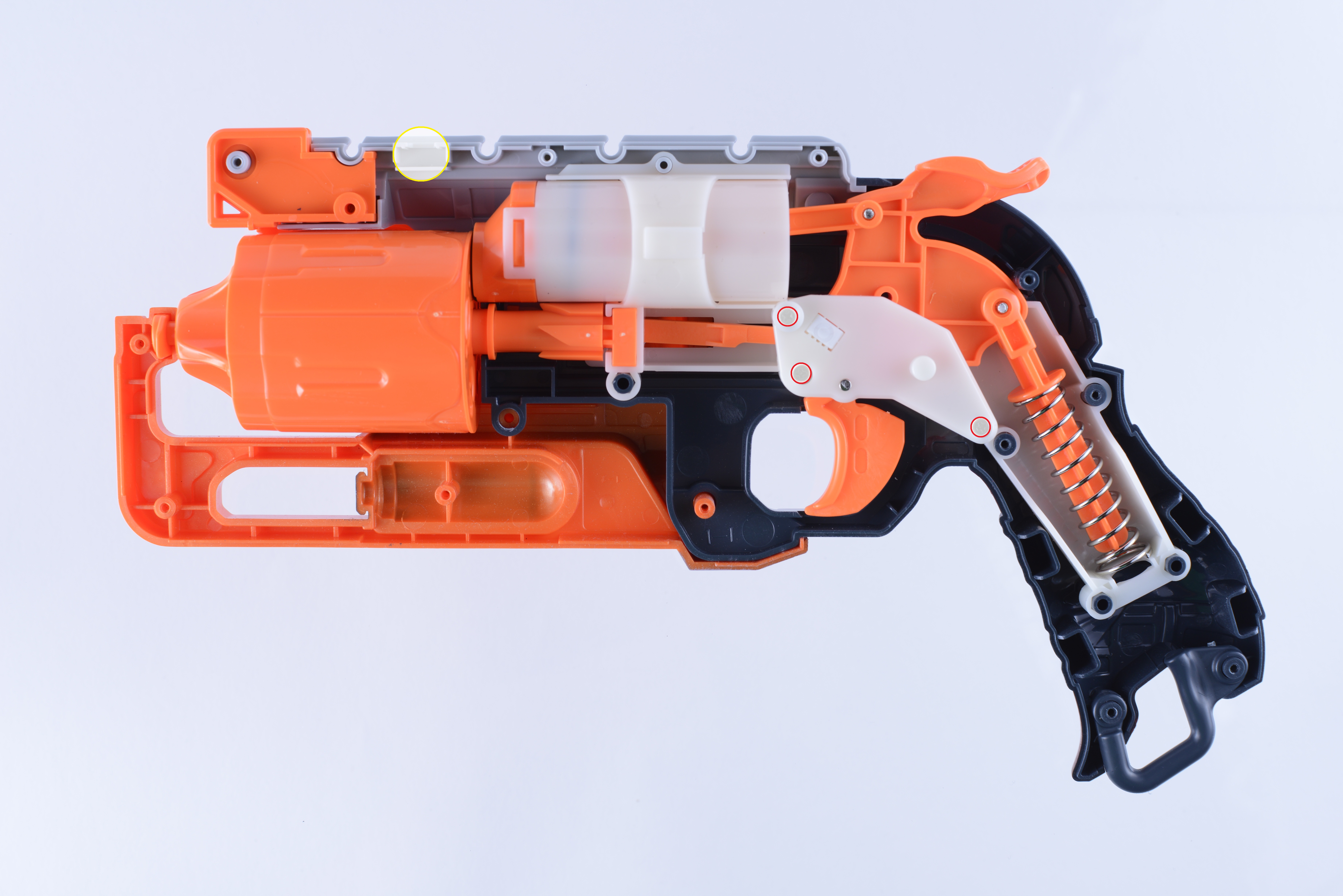
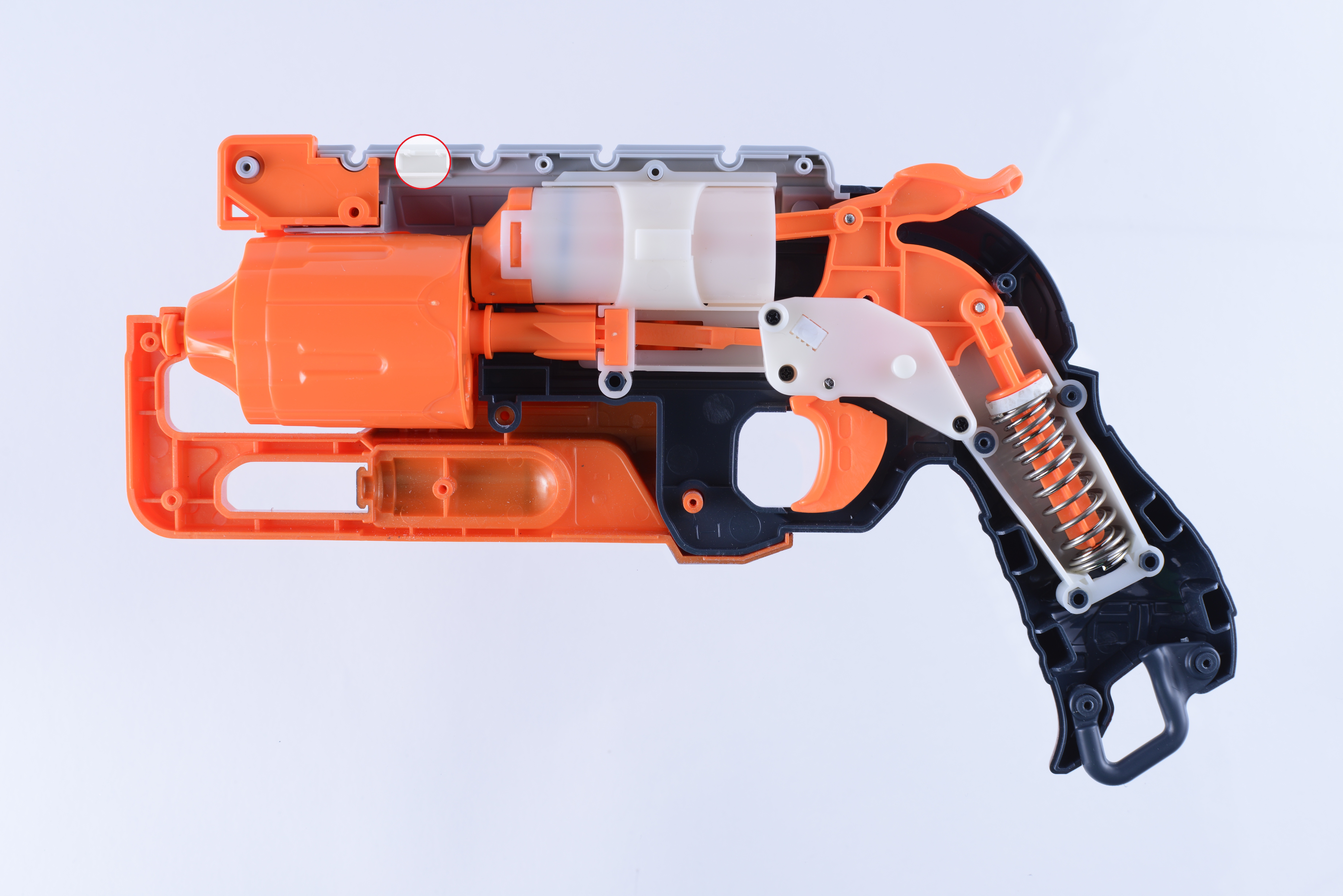
The three screws indicated in the following picture do not need to be removed for basic disassembly. At this point, take out the tactical rail lock indicated with the yellow circle, to ensure you do not lose it. You may remove the screws shown by the red circles if you want to remove the air restrictor from the rear of the plunger tube face. but take careful note of how to reassemble it. If you do do this, you also have an opportunity to tighten the air seal of the plunger by wrapping two wraps of teflon tape under the o-ring. It is not necessary, but is an optional step.
Fig. E2.1 - Internal plunger assembly and rail lock position
-
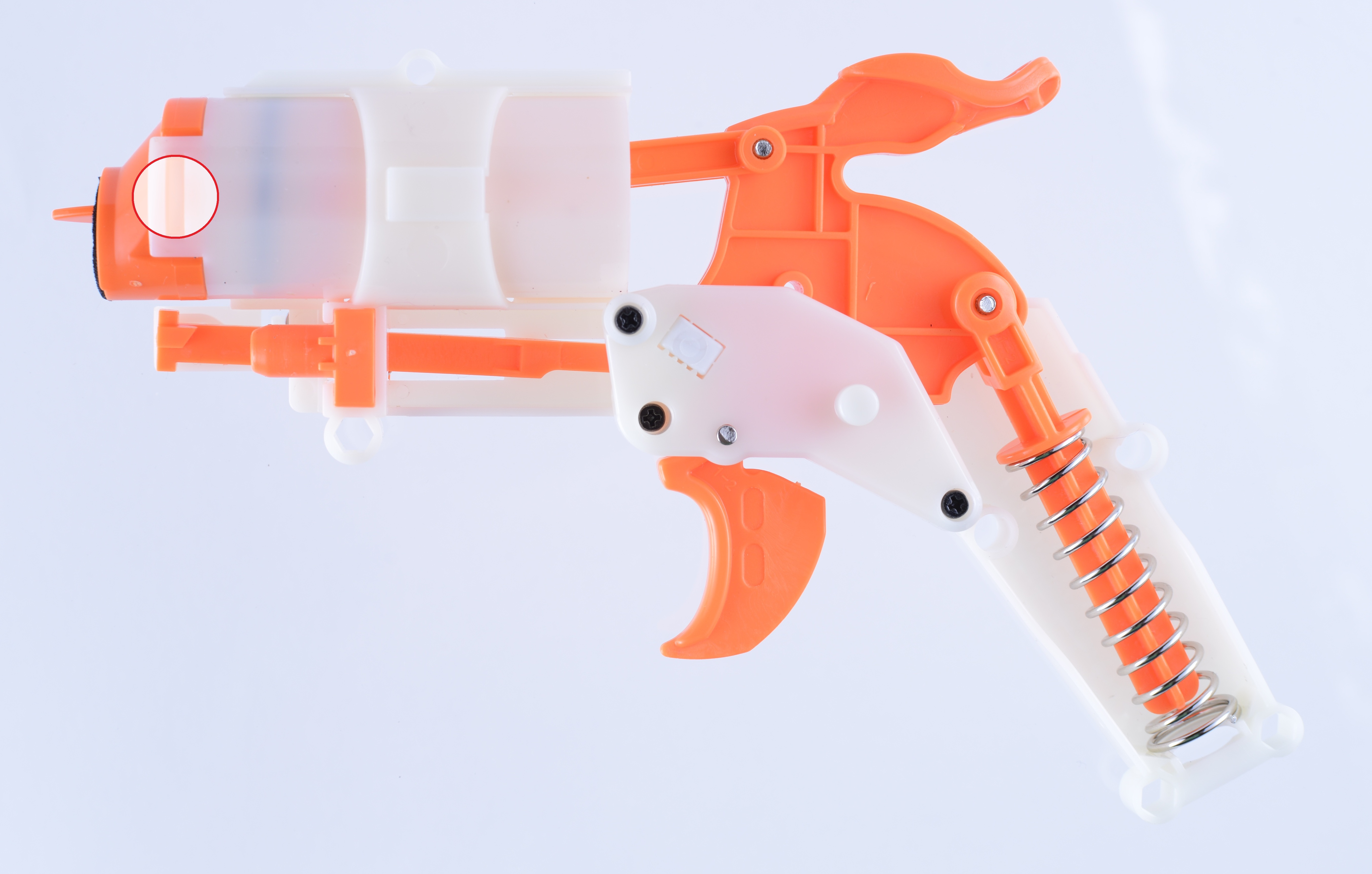
After removing the plunger assembly from the shell, you can see the tab indicated below with a red circle. You may want to either remove or tape down the orange bit directly below the plunger, to prevent it from falling out during modification.
Fig. E3.1 - Plunger assembly as removed from shell
-
In the picture below, one can see the second tab, as indicated in red. The spring indicated by the yellow circle should be taken off and placed somewhere for safe keeping, during modification. Losing this spring will prevent proper rotation.
Fig. E4.1 - Plunger assembly opposite side, rotation mechanism spring position
Take care during the next step. Lift one of the pry tabs indicated carefully using a small flathead screwdriver and slide the orange plunger cap out, using the opposite side as a pivot point. This will give you access to the air restrictor.
-
In the picture below, you can see the orange plunger cap after separation from the plunger tube assembly. To increase air flow and complete air restrictor removal, cut across the red lines indicated in the left hand picture with a pair of dikes. In the picture adjacent to it, the plastic strip has been removed, and the hole has been widened.
Fig. E5.1 - Plunger cap
(Optional) If you so wish, the cap can be filled with hot glue or some other material to reduce a small amount of "deadspace". The idea behind deadspace is that unused volume or space within the plunger assembly and the barrel decreases potential pressure behind the dart. There isn't a huge amount of deadspace in this system, and as such, it is a difficult modification for one to verify its effectiveness. For one of the Hammershots we modified, the deadspace was ras reduced, but the opening was kept as wide as the widened opening of the plunger cap.
-
To complete the removal of the air restrictor assembly, cut along the supports marked with red lines in the following picture, using your dikes. Now is a good time to clean up the cuts with a file.
Fig. E6.1 - Removal of air restrictor support from plunger tube
Now would be an excellent time to apply silicone lubricant to the inside of the plunger before reassembling it. Also be sure to clean out any plastic bits that have been left over from the air restrictor removal. If you wish, it is also a good time to apply a layer of Teflon tape under the o-ring. One or two wraps is sufficient. Any more and it applies too much friction to the plunger tube wall. Re-lubricate the o-ring as necessary. You are now ready to place the plunger cap back on. Before doing so, it is a good idea to apply lubrication between the two mating surfaces of the plunger cap and tube. This will provide a better air seal.
-
To remove the dart posts and allow your Hammershot to use any type of dart, cut your cylinder's dart post supports as shown. Cleaning the support cuts with a file is recommended, to allow for smooth rotation of the cylinder and prevent possible damage to darts due to sharp edges.
Fig. E7.1 - Cylinder with removed dart posts
-
The purpose of spacers is to increase
the spring compression. It is made slightly wider than the orange spring
rest at the top of the shaft to accommodate a larger outer spring for nesting. This increases the spring compression when primed to nearly 100% and this method is much more durable than hot glue. Additionally, should you have an extra
Retaliator/Rampage/Elite Alpha Trooper spring, it can nest over the
stock Hammershot spring. This guide uses an 8kg spring purchased from
SGNerf. A stock Retaliator spring adds a good amount of strength and depending on the spacing length, may provide more force than some people can prime with a
single thumb.
Homemade PVC spacers (skip to McMaster spacers section below if you are using McMaster spacers):
For the purpose of this guide, and in the interest of time, a spacer was shaped from heat treated and flattened PVC.
 Fig. E8.1 - PVC spring compression spacer
The outer diameter should be approximately 3/4" (~19mm), and the inner diameter should be approximately 3/8" (~7mm). The thickness of a single spacer is approximately 0.14"-0.16". This dimension may vary with the flattening process. It is possible to fit up to 3 of these PVC spacers in between the spring and the top of the spring rest. Of course, you can use less at your own discretion.
For smooth priming action, we recommend trimming the spacer along the red lines indicated above. A file or a dremel can be used to do so. Position the flat sides facing the screw posts (not shown in pictures below). This will allow the spacer to glide through without rubbing the plunger assembly. It should not rotate once the spring is applying pressure against it. However, it may be prudent to apply a small amount of hot glue to the top, to hold it in place and to prevent any possible rotation.
We here at Better Nerf By Science have found it to still be manageable with both an 8kg SGNerf spring and a stock spring, with 3 spacers. Depending on the number of spacers and the nested spring used, it may take some trial and error to determine the optimal system for your needs.
McMaster spacers:
The McMaster spacer shown in Fig. E8.2 is the longer, 1/2 in. length one. These lengthier ones will work perfectly with stock Maverick springs (also shown in the same picture). Whether this spacer will work with the upgrade Maverick springs is untested and unknown. It may be possible to use these spacers with stock/upgrade Retaliator springs. But because the spacer is so long, it becomes very difficult to push the nested springs inside the inner shell spring housing. I seem to recall catch issues with this setup as well, or maybe it is because I thought the blaster will break with the setup that I refrained from this build. The stock/upgrade Retaliator spacer I linked above is 3/8 in. in length. I have not tested this spacer length myself but I am confident that this spacer, along with using a stock Retaliator spring as the outer nest spring will be the perfect build for most people. More specifically, this setup should still be very prime-able with one thumb/hand while maintaining a good balance of power, reliability and durability. If you want to experiment various spacer lengths with various springs, we recommend getting the longer spacers (the ones linked for stock Maverick springs) and shaving them down to the desired length for experimentation/modification.
The pre-made McMasters spacers are pretty much ready to install right out of the box. Here is an example of a completely unmodified McMaster spacer in the Hammershot: Fig. E8.2 - McMaster spacer in Hammershot
Here is a picture of the spacer by itself: Fig. E8.3 - McMaster spacer
The picture above shows the side of the spacer where there is a small lip from the normal face of the side to the inner cut-out cylinder. Although this is not specified in the product's datasheet, it is an advantageous feature for us because it is the perfect housing for the coned top of the stock spring. So place this side of the spacer towards the spring(s).
Although the spacer will work out of the box, you might want to modify it slightly for optimal performance in your Hammershot. The large outer diameter of the stock spacer will grind along the inner shell's seat-post housings during priming and releasing of the spring. Grind the spacer's sides to prevent this from degrading performance. Refer to Fig. E8.1 to see approximately how much to shave off.

-
It is now time to reassemble the blaster. Remember to place the tactical rail lock back in (shown with a red circle in Fig. E9.1). Also, do not forget the spring mentioned in step 4, it must be placed correctly to ensure proper rotation. Notice the nested 8kg SGNerf spring with a single PVC spacer. Remember that the stock spring's wider opening rests on the bottom. We recommend making sure the openings of each spring face opposite each other, where the outer nested spring has its opening facing the inside of the shell. You may find it difficult to insert both springs, especially under increased compression, but it is possible. Exercise caution, as the springs may pop out of position during reassembly. Try to position the spring flex away from the shell half you are installing on top, so that it does not press against the shell and hinder reassembly.
Fig. E9.1 - Reassembly
It may also be prudent to apply a small amount of lubrication to the outside of the plunger, along the white support area highlighted by yellow circles, to ensure smooth cylinder air sealing action. This is because the plunger slides forward to form a seal against the cylinder.
 Fig. E9.2 - Reassembly, with highlighted areas of interest
You may encounter a sealing problem with the blaster's rotation mechanism. Under high spring compression, the blaster had trouble sometimes properly rotating the cylinder. This would prevent a proper air seal from forming. There were two solutions found to work on this problem. One was to add a dab of super glue between the rotation mechanism highlighted by the blue oval and its support, to keep it from moving. The other solution was to place maybe less than a tenth of an inch of hot glue to the top of the rotation mechanism. This causes it to press against the other half of the shell more, preventing any sort of play in its movement.
 Fig. E9.3 - Suggested order of screw reassembly
In the above diagram, some screw positions have been suggested to be placed first. This is done to secure springs and rotation mechanism first, as looseness in either area can cause problems during reassembly otherwise. The order is also influenced by doing opposite screw positions to optimize pressure on those portions of the shell as well.
There are some other things to note when reassembling your blaster. You will no longer experience a click when manually rotating your cylinder, as this click was caused by the air restrictor moving from barrel to barrel. However, this should not affect your seal as when the blaster is primed, it will line up the barrels correctly, provided you assembled the rotation mechanism correctly.
Another thing to note is that it may be better to place one spacer on top, and the remaining spacer(s) on bottom, if you can shape the spacers to fit on the bottom. The reason being that the spring will be moving less mass, albeit slightly less mass, so more of its power is used to project the dart. This is mentioned because people may not use light material like the PVC spacer made here, or the nylon mentioned. It is possible to use other appropriately sized materials, like metal washers.


The concept of deadspace is a very old one in the Nerf modding community. It submits that a reduction in unused volume in a plunger system will increase the pressure exerted on the dart. We can verify this by thinking about the ideal gas law.
Fig F1.1 - Ideal Gas Law
Where n is the number of moles, R is the constant of the gas in question, and T is temperature. We can view the entire right side of the equation as a constant in our system. In the rewritten equation below, we can see the inverse relation between the two. By moving V to the right side, we can see that as V increase, pressure decreases.
Fig F1.2 - Ideal Gas Law, rewritten
This brings us to the question of the importance of deadspace reduction. By calculating the volume of the front plunger cap before and after deadspace reduction, we can see how much it may make a difference.

Fig F1.3 - Plunger tube cap measurements
Here are some measurements taken. They are rough measurements, and some simplifications will be made to make the math easier. Without getting too much into it, these are the relevant equations. There is a limitation to the dimensions that can be measured within this system. We will be assuming ideal conditions.

Fig F1.4 - Equations for volume of the plunger cap
Eq.2 is the volume of the red section displayed in Fig. F1.1, Eq.3 is the volume of the yellow section, and Eq.4 is the volume of the blue section. Equation 4 is a simplified version of the math, that should be good enough for our purposes. The blue section has been modeled as a truncated cone, despite one end being an ellipse. The math for the true model ends up being more complex than is really needed. An approximation of the exact dimensions will be more than enough for our purposes. In any case, the combined plunger cap volume can be estimated to be 0.4238656 inches cubed. Eq.5 is the volume of the plunger cap once one has reduced deadspace. This is almost 1/4 the volume of the original plunger cap.

Fig F1.5 - Equations for volume of the plunger tube
Eq.6 is the volume of the unused portion of the plunger tube. Eq.7 is the volume of the effective plunger tube. These numbers do not take into account the travel of the plunger tube when it slides forward for the seal. Adding the unused plunger tube to the original plunger cap, we have 0.7116106 inches cubed. That's almost as much as the effective plunger, nearly 71% of the effective volume. With reduced deadspace, we have 0.387459 inches cubed. That's nearly half of the original deadspace, a non-insignificant number.
Unfortunately, we cannot truly calculate the effectiveness of the deadspace reduction, or cannot say there is a direct correlation between pressure and volume in our system, since we cannot currently measure the speed of the plunger or the pressure that it compresses the volume of the effective plunger to. But it is easy to see that in the equation, this is a significant amount of volume reduction, which due to the inverse relation of pressure and volume, as related to us by the ideal gas law, we can see that there will be a noticeable increase in pressure.
What interests me is the tapering at the plunger's outlet, a sort of Venturi Effect maybe? If so, then filling the deadspace could potentially reduce air delivery efficiency. Or, is the scale to small for either of these to affect the blaster's performance you think?
ReplyDeleteThis comment has been removed by the author.
DeleteThis is exactly why I was against the whole deadspace removal at first and argued with naazrael lol.
DeleteThere is a proper engineering model to model this effect (I forgot the name). But essentially, it interrelates pressure and speed. I think in this case, as long as you leave a big enough hole (as big as the widened exit hole at the end of the plunger) in your deadspace removal process, the venturi effect should still be the non-dominate degrading factor and the effects of deadspace removal is still positive.
A good way to easily achieve this type of deadspace removal is getting any type of piping that has a inner diameter that is as wide as the exit hole and has a outer diameter that will fit in the plunger cone head. Then you can hot glue this piping into the plunger cone head. The smoothness of the piping sidewalls will decrease air scatter and ensure smoother air flow as well, compared to using hot glue alone (rough sidewall surfaces).
Modeling this properly would take a bit of time. But the real reason why modeling may be pointless is that you can never be sure of its results. Instead, we plan on chronnying a blaster with deadspace removal and one without for comparison. I think we should be able to see a few fps gains in the one with removed deadspace.
Here is some relevant information:
Deletehttp://www.roymech.co.uk/Related/Fluids/Fluids_Pipe.html
scroll all the way to the bottom, to the sudden expansion, sudden contraction and orifice part
teehee you said orifice.
DeleteYou obviously know some physics. Have you thought about the corilation between the volume of compression and the force on the plunger by the spring? As well as spring constant? Also why inches?.. Other than that this is really awesome! I haven't seen moders use actual physics to justify their modding!
ReplyDeleteNotice that I mention that the speed of the plunger cannot be measured. The speed of the plunger is directly related to the force exerted by the spring, no?
DeleteSo then all we can estimate is maximum compression and minimum compression volume. Hence why I decided the effectiveness of the modification was inconclusive.
FPS tests will only tell us so much - yes there may be some minute measurable difference, but how can we can differentiate that from shot to shot inconsistencies, which are very significant?
But I think that asking the question is just as important as finding an answer. That's why I wrote about the basic physics behind it, even if I did not believe there was a definite conclusion.
This comment has been removed by the author.
ReplyDeleteDid you already figure it out? The air restrictor is the only reason why it's not free spinning originally. Once you prime it, it will align.
DeleteThis guide aims to cover modifications to the Nerf Zombie Strike Hammershot. ... nretaliator.blogspot.de
ReplyDeleteI am having a problem with the rotating mech.
ReplyDeleteI removed the AR and when I did the orange spring hook on the rotating mech snapped, I replaced it with a small screw and nut and the first prime alway works, however it doesnt prime it far enough for the catch to rotate it a second time. I have glued the orange bit in as was mentioned above, and it seems to be more related to the plunger moving, however that only fixes it inconsitantly. Is the force of the AR being removed screwing with the rotation mech? Because I cannot for the life of me figure out how to fix it permanantly.
I don't think the AR being removed would do that. It probably has to do with the implementation of your replacement spring hook. Maybe it's exerting too much or not enough force. If moving it isn't possible, perhaps try a weaker or stronger spring.
DeleteThanks, I'll try that.
DeleteI created a 3d Printable spacer for the hammershot using this guide and my own testing.
ReplyDeleteThanks for the great guide
http://www.thingiverse.com/thing:904814
Dude, please make more mod guides like this. This one was amazing with its level of detail, clarity, and research.
ReplyDeleteI would only ask for more images for intermediate steps, i.e. undoing the pry tabs via screwdriver. I was trying to be as careful as I could and still ended up breaking BOTH of them (not the end of the world; just hot glued it back in place when I was done). More pics to illustrate exact technique might've helped.
But anyways, more guides like this please!
so.........would you sell this mod to me? $$$
ReplyDeleteAwesome Article. You can also visit http://besttopreviewsonline.com/blog/best-nerf-gun-ever/ to read reviews on best nerf gun
ReplyDeleteHey azrael, nice article. I'd like to email you about it if possible.
ReplyDelete