


Table of Contents
A. Introduction
B. Compatibility
C. Tools
D. Parts
E. Modifications
F. Appendix
FA1: How to unscrew and screw screws correctly
FA2: How to desolder and solder correctly
FA3: How to break-in electrical motors
FB1: How to select an electrical power system: motor and battery
Welcome
to the Rayven's edition of The Works Guide series. This guide will
cover a complete rebuild of the Nerf Rayven blaster's electrical
system. Instead of using simple contact switches, a relay system will
be implemented to allow higher current limitations for aftermarket
motors. This guide will also go through the motor and battery
replacement process, as well as removal of all locks and other
optional upgrades.
More after the jump!
Although
the main focus of this guide is original, many portions of the
modification are repeated from other guides/posts for completeness.
It is difficult to accredit everyone for their contribution, but this
is mentioned to support the community. Here at Better Nerf by
Science, clarity and documentation are also keenly focused to make
these guides as easy to follow as possible and allow the creation of
an awesome blaster!
The
only part of this guide that must be strictly followed is the
electrical wiring section. The locks removal is optional and this
modification will work with them intact. The motor and battery system
is also interchangeable with any system that is compatible with the
blaster as well as with each other.
Note:
Any tool that fits the listed description can be used. The first
specific item below the description is the tool used in making this
guide. Additional options may be shown.
Required:
- Soldering iron
-Hakko FX-888: amazon - Small flat head screwdriver
- Stanley Jewelers Precision Screwdriver Set: amazon - Hot glue gun
- Wide pliers
- Hand drill or drill press
- (double shaft motors only) Dremel or hacksaw or heavy duty cutters
-Dremel 400 XPR (old tool, many newer alternatives now)
Recommended:
- File or sandpaper
- Wire stripper
- Dremel
- An assistant
Note:
Any part that fits the listed description can be used. The first
specific item below the description is the part used in making this
guide. Additional options may be shown.
Electrical
system overhaul:
- Low resistance wire
Note: Teflon wires are used in making this guide. They provide excellent high temperature protection such as fires. However, they are very stiff and put a lot of stress on wire joints. If stress relieve is not implemented on these joints, they will eventually break under vibration or shock. Silicon wires are recommended because they are flexible and do not stress the joints, making them reliable.
-Gore 22 AWG Silver Plated Tri Insulation Teflon Kapton Wire 19 strands: ebay (white) ebay (red)
-Turnigy Pure-Silicone Wire 18 AWG: Hobbyking (black) Hobbyking (red)
-Turnigy Pure-Silicone Wire 18 AWG: Hobbyking (black) Hobbyking (red) - Single pole double throw (SPDT) relay (select one that matches the battery voltage!)
-Generic 6 V 10 A SPDT relay (bought at local electronic shop)
-Turn On Voltage range: 2.94V - 6.3V (1 cell LiPo): Mouser-Turn On Voltage range: 9V - 13.5V (3 cell LiPo): Mouser - Wire wrap
-Heat shrink (match wire gauge, highly recommended, available at local electronic shops such as Frys)
-Electrical tape
Recommended
power system replacements (motors and battery):
Note:
refer to FA3: How to break-in electrical motors in the Appendix
section at the end of the guide for more information and/or to create
a custom combination.
- Tamiyas and LiPo - used in this guide and conservatively tested. This setup does over volt the motors quite a bit and the brushes or motors may have to be replaced periodically with heavy use. See option 2 for a more durable setup.
~2x Tamiya JR Mach-Dash Motor PRO: Hobbylinc
~Gens Ace LIPO Battery 4300MAH 30C 7.4V: Hobbypartz
Note: this package comes with two separate hard case single celled LiPo batteries, only one battery will be used at a time. - PNs and LiPo – if money is not an issue, this is the best system possible with 130-sized brushed DC motors. With more than ten times the Mach Dash Pro's torque (PN @ 4.2 V), the PN racing motor uses neo magnets, ball bearings and carbon brushes, outputting the maximum performance possible. This system works amazingly with 1s LiPos (4.2 V) and is very reliable at this voltage. The motors can handle 2s LiPos (8.4 V), but they spin so fast that the flywheels do not have enough grip onto the motor shafts and will slowly come off the motors until they rub against the motor cage. Gluing the flywheels to the motor shafts is not recommended as it will render the system permanent.
~2x PN Racing Mini-Z PNWC Ball Bearing Motor 32 Turn – Kenonhobby
~Gens Ace LIPO Battery 4300MAH 30C 7.4V: Hobbypartz
Note: this package comes with two separate hard case single celled LiPo batteries, only one battery will be used at a time. - Tamiyas and rechargeable lithium batteries - untested, see note below.
~2x Tamiya JR Mach-Dash Motor PRO: Hobbylinc
~3.7 V 18650 3600 mAh rechargeable lithium battery: Amazon
Note: the two batteries that comes with this package must be paralleled in order for this system to work properly. The protection circuit might pose a problem if it is set trigger at a current that is less than the maximum output current. - RM2s and LiPo
~2x Solarbotics RM2: Pololu
~GENS ACE 1300mAh 25C 11.1V LiPo Battery: Hobbypartz
Note: Some people have used this setup with varying degrees of success. They have reported brush failures with RM2s. It may not be recommended to use them with higher than 2s.
(optional)
Noise/vibration reduction:
- Vibration reduction material
~craft foam
~Dynamat (high quality vibration dampening): ebay
Note:
be sure to read an entire numbered section before proceeding each
step.
- Open the blaster
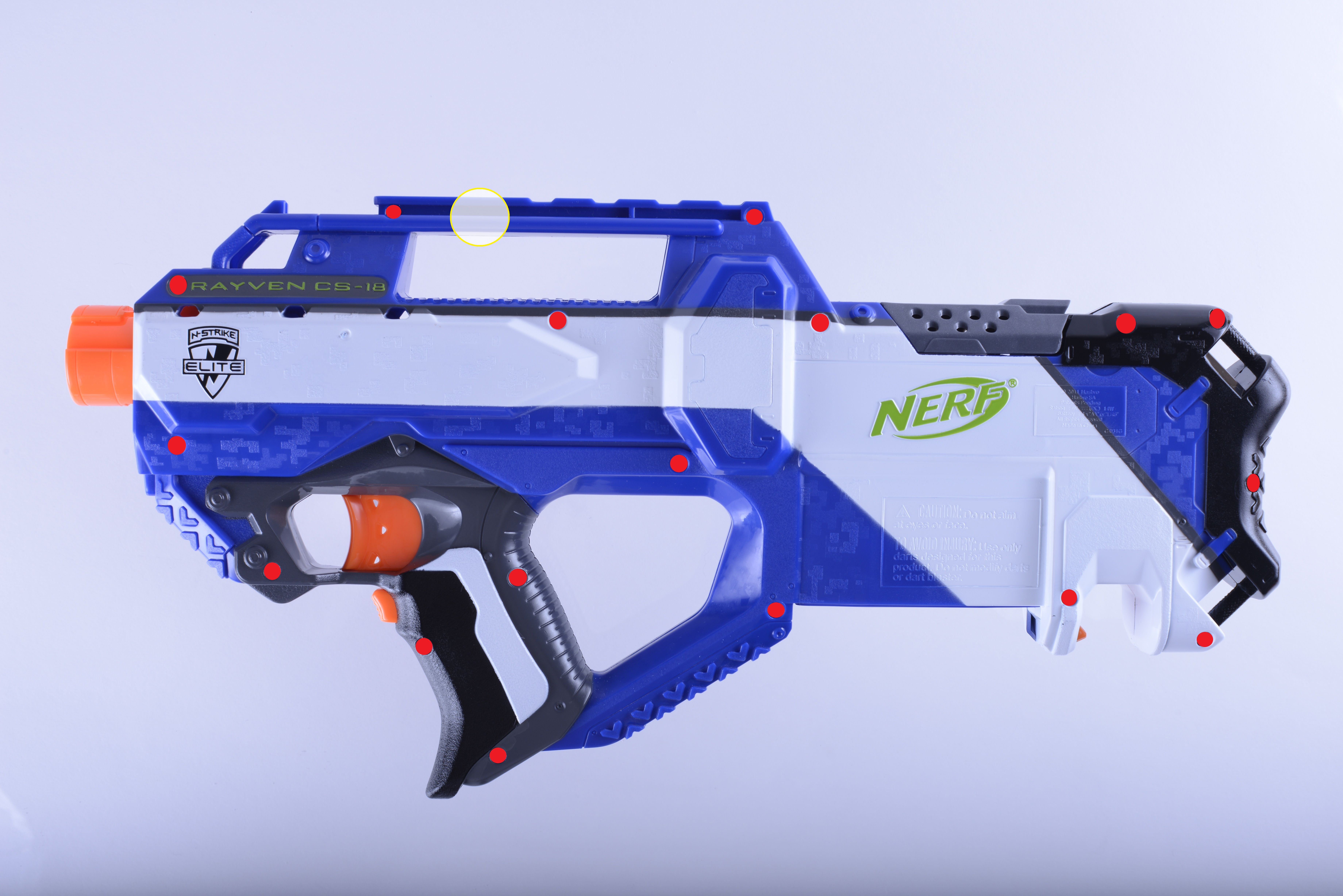
Remove the 17 screws indicated below in red and gently pry open the blaster. The tactical rail is a good place to start splitting the blaster. Beware of the tactical rail lock spring that may fly out. Fig. E1.1 – Rayven screws and rail lock locations
- Thermoresist and inductors removal
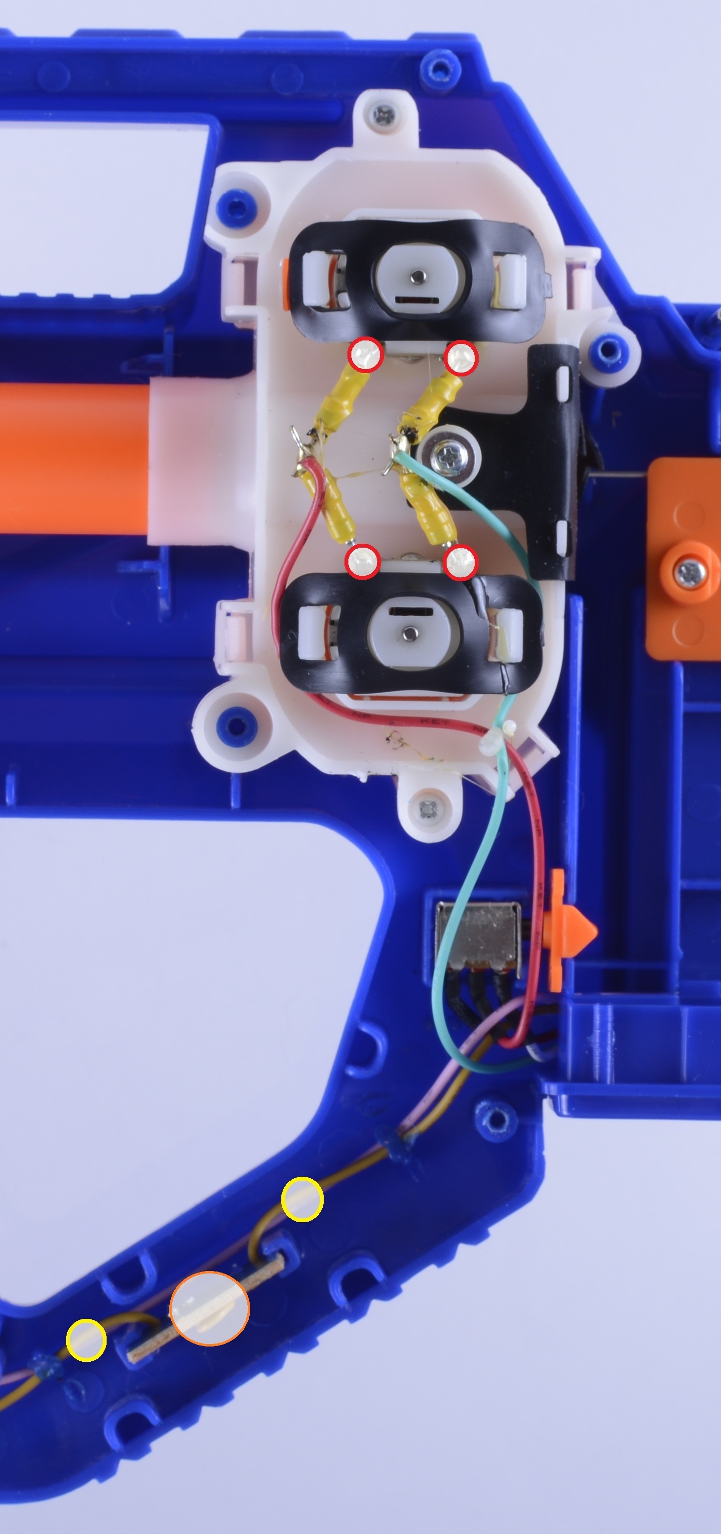
Thermoresists create electrical resistance in series with the motor when it is heated from high current draw. They are designed to protect the stock motors from stalling when a dart jams the flywheels. Removing the thermoresists is necessary for high power systems as they will trigger the thermoresists almost instantly under normal operation. The inductors prevent the electrical noise created by the brushed motors from reaching the power lines. It effectively does the same thing as putting capacitors across the motor terminals. These techniques are used to reduce electrical noise on the power lines of the system. Since there are no electrical signals in this system, these devices are not necessary. Remove the inductors by unsoldering the joints circled below in red. Cut the wires circled below in yellow and pull out the theromoresist PCB circled below in orange.
 Fig. E2.1 – Thermoresists and inductors removal
- (optional) Electrical and mechanical locks removal
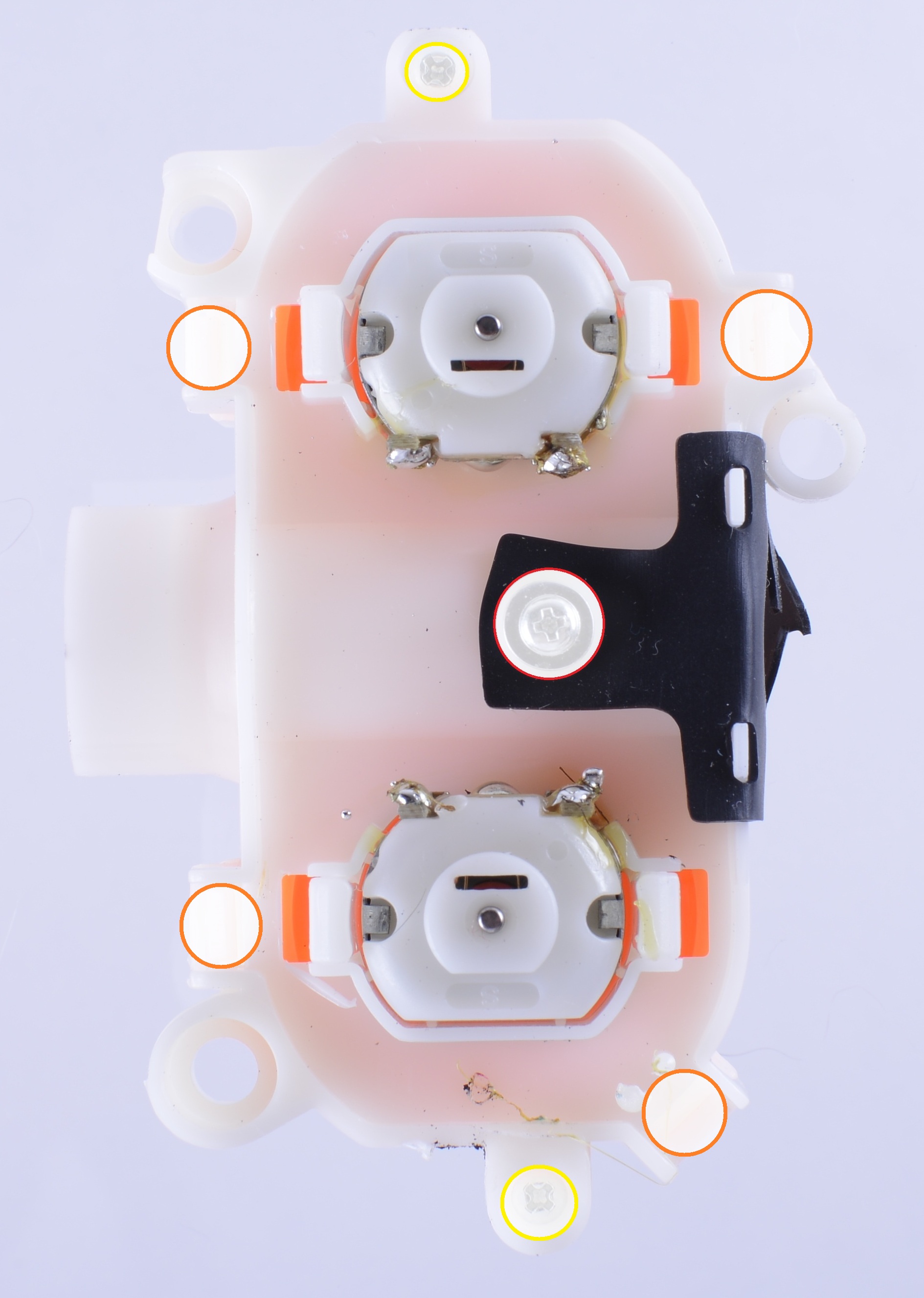
The electrical lock circled below in red brakes the motors when the jam door is opened. The electrical lock circled below in orange brakes the motors when the clip is removed. The mechanical lock circled below in yellow prevents the trigger from being pulled without a clip. The mechanical lock indicated below in green is the accelerator trigger lock. It prevents the trigger from being pulled when the accelerator trigger is not engaged. The removal of this lock is not recommended Accidentally pulling the trigger without powering the motors will push a dart in the flywheels. If the motors are powered when a dart is already in the flywheels, it will jam the motors and stall it, eventually burning it out in a few seconds. Remove the two electronic locks (cut the wires attached to the switches) and their components shown below with three red circles. Remove the two clip lock parts shown below with two yellow circles. Lastly, remove the accelerator trigger pusher circled below in green.
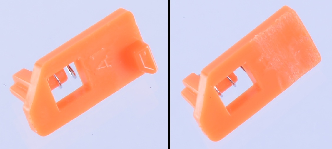
 Fig. E3.1 – locks positionsThe removed accelerator trigger pusher piece needs to be shaved to remove the accelerator trigger lock. This can be done with the utility knife, or more easily with a Dremel, file or sandpaper.
 Fig. E3.2 – stock accelerator trigger pusher on the left, shaved accelerator trigger pusher on the rightBe sure to shave off the lock part completely as indicated above.

- Stock wires removal
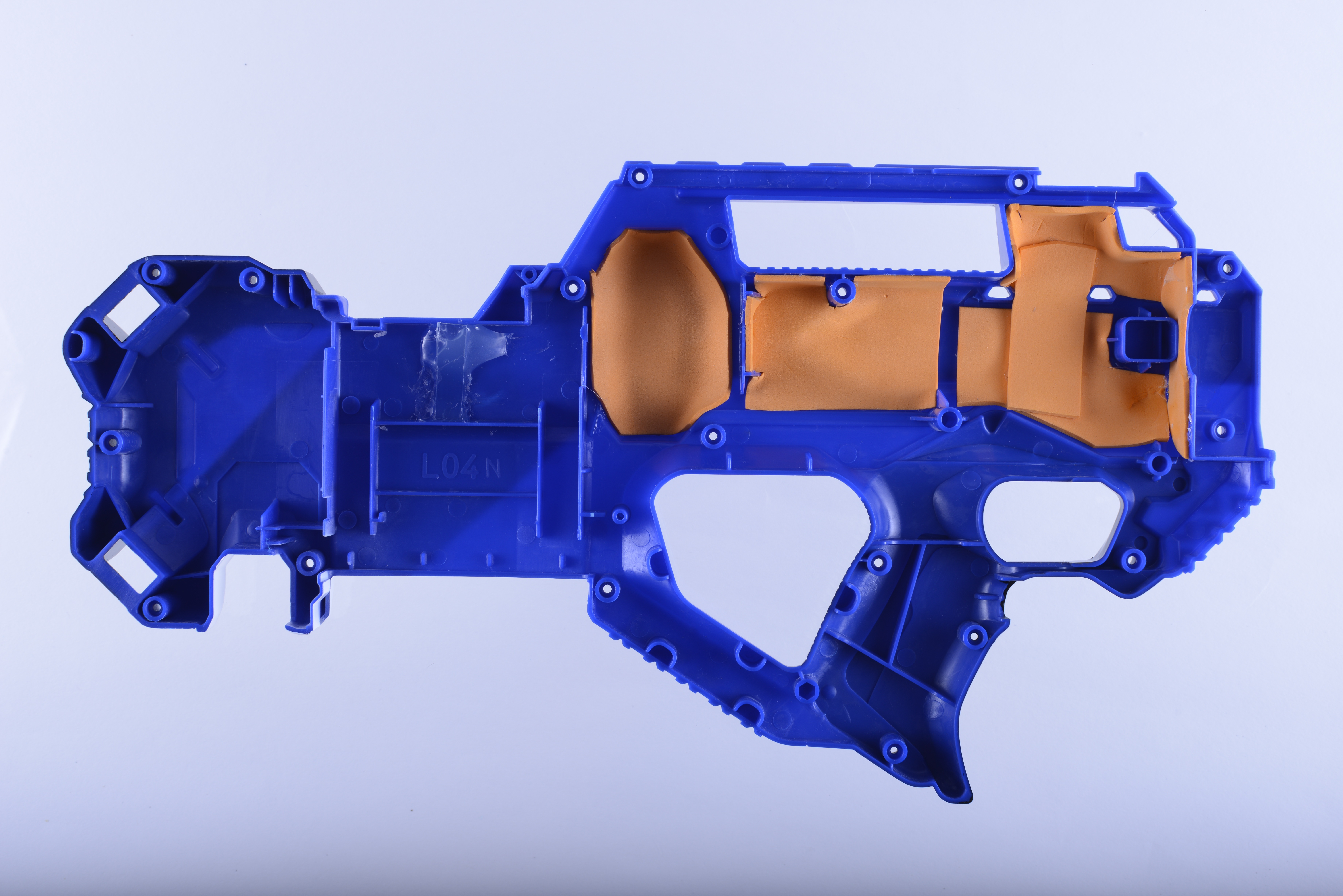
To incorporate a relay, the blaster's electrical system must be reworked. There are probably enough stock wires to implement this, but it is much more convenient and less worrisome to purchase new wires. In addition, the wires can be upgraded to larger gauge, less resistive wires to minimize power transfer loss as well as better insulted wires for improved wire protection. Remove the mag well that guards the battery leads and unsolder the wires from the two battery leads circled below in red. Unsoldering these leads may be difficult. Please read FA2: How to unsolder and solder correctly to easily unsolder these joints. Fig. E4.1 – blaster with stock wires removedThis is what the blaster should look like after all of the locks have been removed (except for the accelerator trigger lock, this was performed later when making this guide). If step 3 was not performed, detach the wires from the two electrical locks by cutting the heat shrink with the utility knife and unsoldering the wires from the switches' leads. Once this is done, all of the stock wires should come out and the blaster should look similar to what is shown in Fig. E4.1, with the appropriate lock switches in place.

- (difficult) Stock motor removal
Lift the motor cage out of the blaster and remove the rubber dart straightener by unscrewing the screw circled below in red along with its equivalent on the opposite side of the motor cage.
 Fig. E5.1 – motor cage dis-assemblySplit apart the motor cage by removing the two screws circled in yellow above and pushing in the four sidewall hooks circled in orange above. Pry off the flywheels with a small flat head screwdriver as shown below. Be sure to extend the flat head screwdriver all to the way to the end of the flywheel so the entry and exit of the screwdriver can be seen. Also note that the flat end of screwdriver should be flesh with the flywheel, as accidently incorrectly shown in the figure below. If possible, insert another flat head screwdriver to the other side of the same flywheel to prop it off symmetrically.
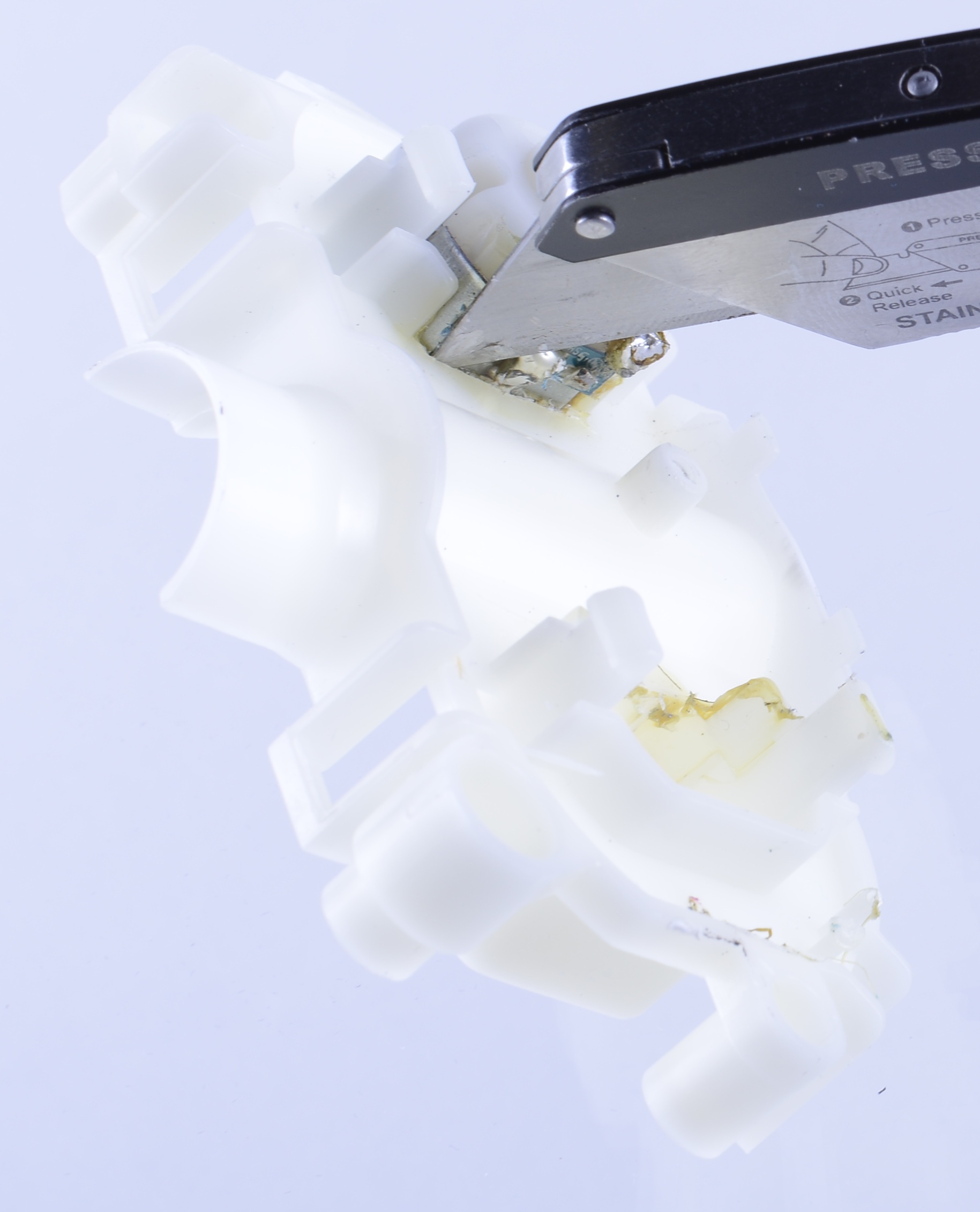
 Fig. E5.2 – flywheel removalCut the yellow glue gluing the motors to the motor cage with the utility knife as shown below. Be sure to cut deep, straight into the cage as the glue may extend well into the cage.
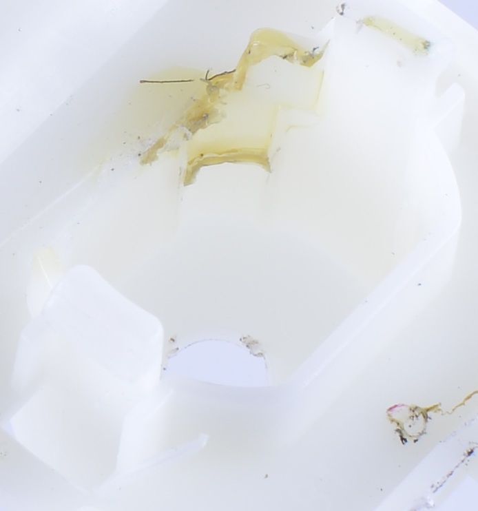
 Fig. E5.3 – motor glue removalThe extent of the glue into the motor cage is shown below for reference.
 Fig. E5.4 – motor glue extension referenceRemoving the stock motors without damaging them can be quite difficult. To do so would require pulling out the motors without pushing on the shafts, as pressuring the shafts hard will damage the motors. This may be easy if the glue is thoroughly removed. But if the glue extends deep into the motor cage, doing so might be challenging. If the motors do not need to be preserved (RM2s are a good direct replacement to the stock motors), it is possible to pop off the motors by pushing hard on the motor cage to a hard surface with the motor shaft being the only contact to the surface. Warning, this process may damage the surface. Be sure to use a non-valuable and/or protected surface. If only the top part of the motor comes off, use the wide pliers to bend both of the straight parts of the remaining metal motor case inward and slowly twist it back and forth until it comes off. If necessary, use the utility knife to cut into the extended glue as access is gained through bending the metal motor case. Be sure to pay attention to how the case is being bent/twisted as doing so in a certain way may conversely make it harder to remove.

- New motors break-in
Put the new motors into the motor cage without the flywheels and clip in the rubber motor holders. Wire the motors in series to the new system battery. Refer to FA3: How to break-in electrical motors in the Appendix section at the end of the guide for complete instructions. Follow the instructions carefully and do not skip any parts.
- (optional) Trigger linkage rub fix
Shave off the trigger linkage movement restriction as shown below to improve trigger performance. This can be done with a filer, Dremel or hand drill. Fig. E7.1 – trigger linkage rub fix

- (optional) Noise/vibration reduction
Use Dynamat or craft foam to cover available areas inside the blaster to dampen motor noise. Multiple areas as well as layers can be applied inside the blaster, just make sure that the dampening material does not interfere with mechanical operation and also that the blaster can be reassembled/closed properly. Fig. E8.1 – craft foam fillingIn addition, the motor cages can be hot glued to the blaster frame to further reduce vibration noise. As a small warning, hot glue melts at a relatively low temperature. If this procedure is conducted, keep your blaster stored in a cool area and avoid leaving it in a car during a hot day. Or as an alternative to gluing in your flywheel cage, perhaps the motor cage housing rods (the rods the motor cage slides into on the frame) can be encircled with a layer of electrical type or a few layers of teflon tape. This has not been tested yet and requires a bit more work, but it should dampen the motor cage vibration significantly.
- Electrical rewiring preparation
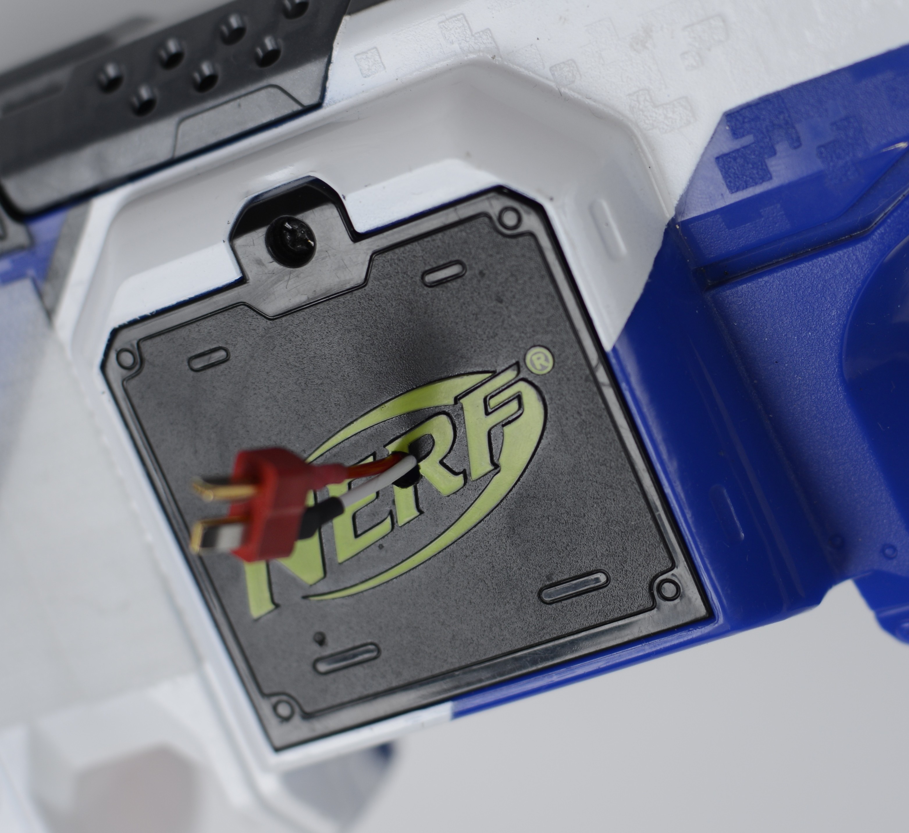
Pop in the flywheels into the new motors and reassemble the motor cage assembly. Check to make sure that the rubber dart straightener is properly wrapped around the motor cage. One of the mounting holes can catch it with its bulge. Slide the motor cage back onto the blaster. If an external battery is used, drill a hole anywhere on the blaster's battery cover, as shown below. Fig. E9.1 – battery cover hole
- Electrical rewiring
The below schematics show the wiring of the new relay system. Fig. 10.1 shows the new system with braking logic (motors brake when the accelerator trigger is released, providing a shorter motor spin down time) and Fig. 10.2 shows the system without braking logic (motors decelerate passively through friction).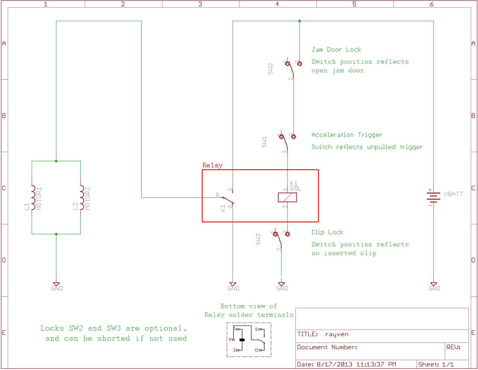 Fig. E10.1 – new relay system with braking logic schematicFig. E10.2 – new relay system without braking logic schematic
 The completed system wiring (with braking logic) is shown below (click on the image to view/download the full image).
 Fig. E10.3 – new system wiring
Carefully and thoroughly examine the system with braking logic schematic (Fig. 10.1) and its correspondence to the physically completed wiring (Fig. 10.3). In the schematics above, VBATT refers to the positive battery voltage. All connections connected to VBATT should be soldered to the stock positive battery tab (the tab closer to the trigger of the blaster). The same applies to the GND destination in the schematics, but soldered to the negative battery tab instead (the tab furthest away from the trigger of the blaster). Even if an external battery is used, soldering the connections to these tabs is essential to hold the wires in place in case the external battery wires are pulled. For selecting the proper switch terminals, when the push button is not pressed, the tab closer to the push button and the middle tab are connected. When the push button is pressed, the middle tab and the tab furthest away from the push button are connected. With this logic and the descriptions within the schematics, it is possible to determine which switch terminals to use. For the acceleration trigger and both of the locks, the middle tab and the tab furthest away from the push button should be used. For these switch cases, the order at which each wire connects to each tab does not matter as long as the two wires leading into and out of the switches on the schematic are used to connect to the two tabs mentioned above. An internal connections diagram for a SPDT relay is shown in the schematic. The terminals in this diagram can be mapped to the relay terminals in the wiring schematic. The terminals labeled 1 and 2 refers to the coil connections on the relay (see relay datasheet). Most modern relays do not have coil biasing, meaning that terminals 1 and 2 can connect to the two wires indicated in the schematic (the ones that are connected to terminals 1 and 2) in any order. However, if the chosen relay does have coil biasing, make sure that the positive coil terminal (the terminal where the current flows into indicated in the relay datasheet) is treated as terminal 1 in the schematics above. For the relay switching connections, terminal P in the schematics above refers to the common terminal (see relay datasheet), terminal O refers to the normally closed terminal (NC, see relay datasheet), and terminal S refers to the normally open terminal (NO, see relay datasheet). Familiarize the desired electrical system (braking/non-braking, locks/no locks) and imaginatively map out its wiring. When convinced of the system's logic and operation, hot glue the relay at a convenient location (see figure above). Trace the new wires corresponding to the new system throughout the blaster and cut them to their appropriate lengths (slightly longer than the traced connection to leave a margin for error). Strip the wires with the utility knife (easier for teflon wires) or wire stripper. Mentally go over the entire electrical logic of the system again and solder the wires once confident to do so. If an external battery is used, do not forget to solder the battery connection wires to the VBATT and GND tabs.
Drill
another hole on the inside of the battery cage to allow the wire to
be fed into the interior of blaster. It is a good idea to offset the
external and internal holes to provide mechanical stress relief for
the joints. If the stock battery cage is used, modify it
appropriately for serial/parallel configuration. No drilling is
necessary in this case.

- Testing
If available, use a multimeter to test the electrical connections with the connectivity test and make sure that the connections match that of the schematic. If a multimeter is not available, trace the wires with a finger to validate circuit path. The connectivity test on a multimeter can also be used across the battery leads to check for a short. Note, pushing the trigger will not trigger a connection for this test as the multimeter does not provide power to turn on the relay. Once the electrical connections are checked, carefully plug in the battery. Do this slowly and if sparks are seen at the connector leads or if the motors turn on, quickly unplug the battery. Otherwise, pull the trigger for a split second right after plugging in the battery and see if the motors spin. If they do not, quickly unplug the battery. If the system does not work, recheck the connections and re-solder joints if necessary. Without a multimeter, it is difficult to debug the system. If the system still remains unresponsive, double check the wiring with the schematic and re-solder every connection.
- Reassembly
Once the system is verified operational, work backwards to reassemble the blaster. Hot gluing loose wires to the blaster is recommended. Make sure everything that came out of the blaster is put back in, including the mag well, tactical rail lock and jam door (optional).
Many people use a screwdriver
without giving it much thought. However, science can be applied to
this process to avoid stripping screws. Luckily, Nerf uses descent
quality screws on their blasters. The most important thing to do when
unscrewing or screwing a screw is to apply as much pressing force as
rotational force, if not more! Pressing force is important because
the contact between the screwdriver to screw is angled upward for
easy insertion of the screwdriver. However, this means that if
insignificant pressing force is applied with strong rotational force,
the screwdriver will slip against the screw and pop out, damaging the
screw.
The size and type of the
screwdriver used is also important. Both attributes contribute to how
flush the screwdriver fits with the screw. In terms of size, never
ever use an undersized screwdriver; if anything, use an oversized
one. When screwing, an undersized screwdriver contact the screw where
it is the weakest and most vulnerable to stripping. In addition, low
profile, flat tip screwdrivers are preferred as they dig into the
screw, maximizing the contact area between the screwdriver and screw.
Jeweler's screwdrivers usually have flatter tips than normal ones. A
figure is shown below to demonstrate flatter screwdriver tips.

Fig. FA1.1
– screwdriver comparison: normal on the left, flatter tip on the
right
It is possible to grind down the tips of normal screwdrivers so they dig deeper into screws and create the same effect as flatter tip screwdrivers. However, purchasing the right screwdrivers (high quality and/or flatter) is recommended over this. How well a screwdriver is paired with the screw can be determine by measuring the screwdriver's fit to the screw. To do this, insert the screwdriver into a fixed screw (screwed-in screw or a screw held tightly with fingers), then lightly press the screwdriver down into the screw and gently turn the screwdriver clockwise and counter-clockwise in a back and forth motion. If the fit is good, there should be very little rotational movement that the screwdriver exhibits during this motion. If the screwdriver rotates significantly, then it is not a good match to use with the screw. The largest Philips screwdriver in the Stanley jeweler's precision screwdriver set is a good screwdriver for Nerf applications: amazon link. Wiha precision screwdrivers work amazingly if quality is desired: amazon link. The Wiha precision screwdrivers exhibit the tip profile of a normal screwdriver as opposed to that of the flatter tip screwdriver. However, they are engineered so precisely that the screwdriver dig deep into the screw to allow the sidewalls of the screwdriver and screw to be perfectly flush with each other.
Another good idea is to layout
the unscrewed screws in positions that correlates to their actual
screw positions on the blaster. This takes up a bit of space, but
with the organization, every screw can be screwed back into the same
screw hole they were unscrewed from. Keeping the screw and screw
holes matched allows for better fitting of the screws. If there is
plastic in between the threads of the screw after removal, clean it
off by squeezing the screw with fingers and rotating the screw
counter-clockwise with a screwdriver. Furthermore, there is also
science behind the order at which the screws are screwed back into
the blaster. The order that the screws should be screwed back in
should start at the center of the body surface and radiate outward.
This means that screws that are nearest to the center of the blaster
shell should be screwed in first while the screws on the edge of the
shell should be screwed in last. If multiple screws are the same
distance away from the center, then randomly select a screw to start
and screw in the remaining screws in an order such that the next
screw is furthest away from the current screw. Examples of correct
screw orders are shown below.
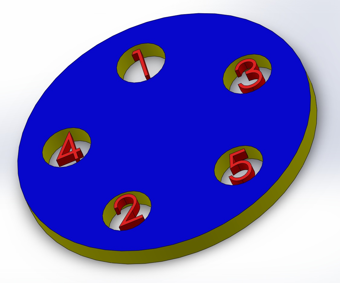
Fig. FA1.2
– equal distance screw order example
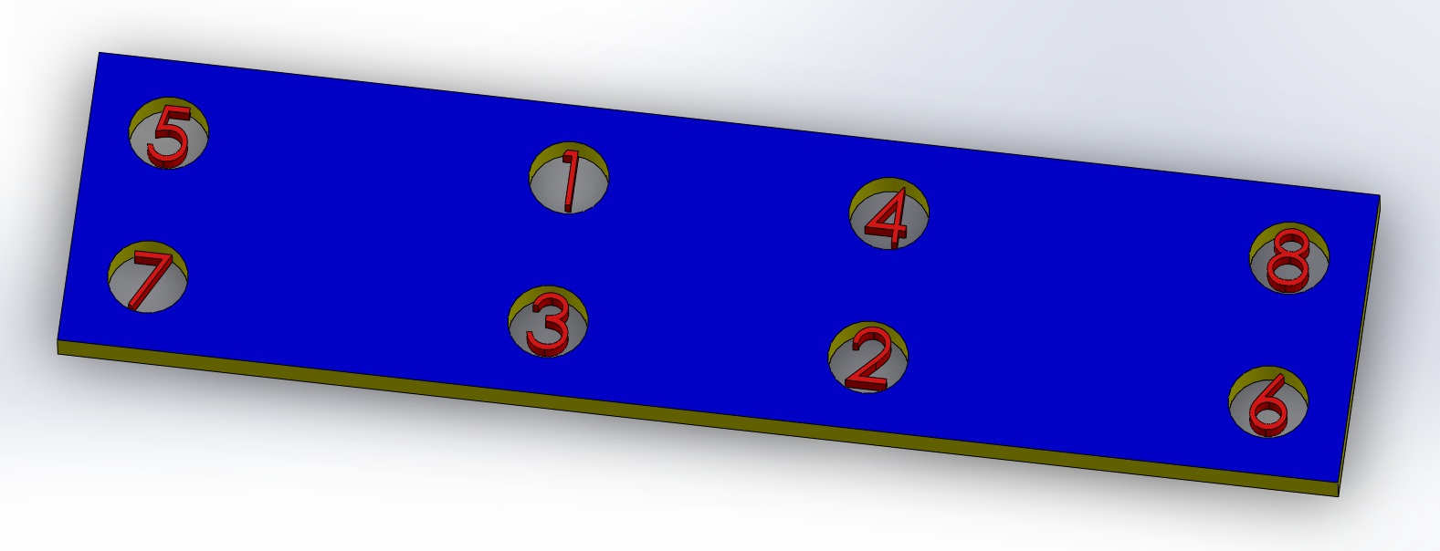
Fig. FA1.3
– radiating and equal distance screw order example
Screwing screws in the correct order reliefs stress on the material body, keeps the joint surfaces flush and allows for more of the screw's retaining force to be used as bonding force.
In standard applications, turn
the screwdriver counter-clockwise to unscrew a screw and clockwise to
screw a screw (lefty loosy righty tighty). If a screw does not loosen
with a good amount of force, double check to make sure that the
screwdriver is being turned counter-clockwise to unscrew the screw.
If screwing in a unique position and/or with the non-dominate hand,
mentally double check the rotation of the applied force for
correctness. In certain situations, it may be necessary to verify the
rotation direction with two or more different thought processes, as a
single method alone may be deceiving. When screwing in a screw, it is
wise to first place the screw in the screw hole, then rotate it in
the loosening direction (yes, loosening!) while holding the screw
perpendicular to the screw hole (either with the other hand or by
tilting the screw with the screwdriver) until a small tick or jolt is
heard/felt. Once this happens, reverse the direction of rotation and
start screwing in the screw normally while maintaining the screw
perpendicular to the screw hole. This process assures that the screw
is aligned to the opening groove of the screw hole from the start and
also prevents misalignment between the screw thread and screw hole
groove. For the first few turns of screwing in a screw, apply gentle
force and turn the screwdriver slowly. If strong resistance is felt
while doing this, it means that the screw thread and screw hole
groove is misaligned. When this occurs, stop screwing immediately,
unscrew the screw and restart the screwing process to correct the
error.
The position where the
screwdriver is gripped to turn it is also a key component of screwing
screws. Screwdrivers have multiple positions to grip for screwing.
The widest gripping area provides the most torque, but is the slowest
screwing speed. The narrowest region provides the fastest screwing
speed, but applies the least torque. The diagram below shows a
cross-section view of a typical screwdriver.
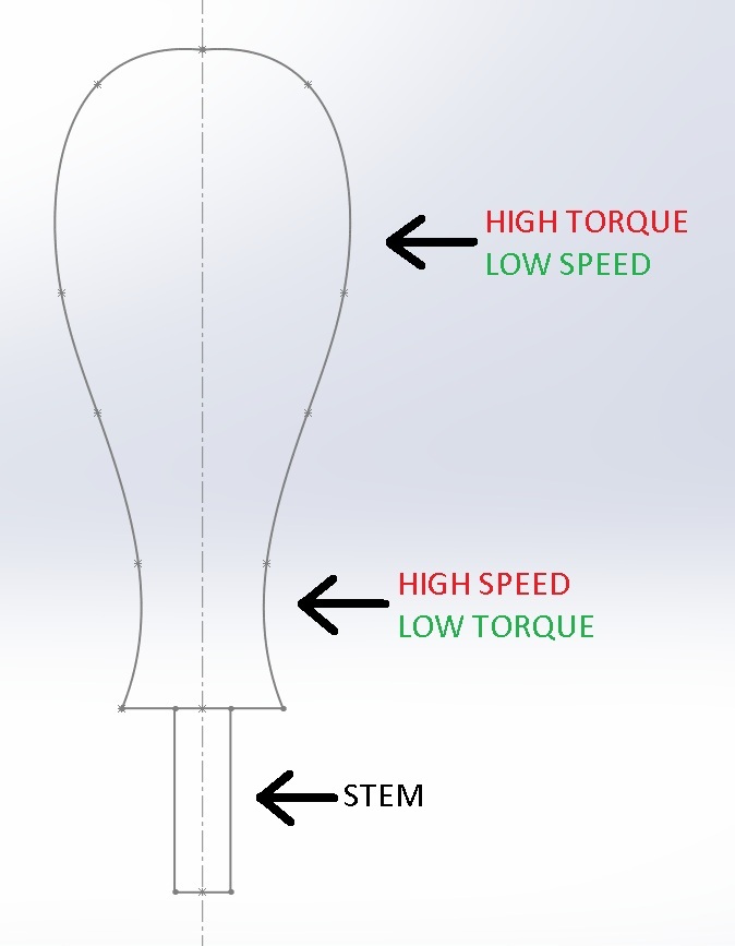
Fig. FA1.4
– screwdriver grip positions
Use the high torque area to break the initial friction when unscrewing a screw or apply sufficient force to finish screwing in a screw. Once the initial friction is broken when unscrewing or initially screwing in the screw, use the high speed area to quickly unscrew or screw a screw. It is also possible to use the stem of the screwdriver to screw even faster! Using the high speed area of the screwdriver's grip or the screwdriver's stem to initially screw in a screw will also make it easier to detect misalignment and potentially cause less damage from this error.
Although most of these tips may
seem pointless, following them will prevent hardware damage and
prolong its life. Once these techniques become familiar, they hardly
require any additional time to carryout. If a screwing job is
necessary, put on some music and do it right from the start!
Soldering
is a skill that is often utilized without much attention. Just
because two joints appear to be physically connected does not mean
that they will make a good electrical connection. As always, the
right tool will make the job infinitely easier. If DIY or custom
projects are always on the menu, it is definitely worth it to invest
in a high quality soldering iron. For occasional users, a basic
soldering iron from a local electronic shop will do, provided that
the proper technique is used along with some aides. It may seem like
high power soldering irons are made for professionals and electrical
engineers. However, basic soldering applications such as power
connections are actually the jobs that demand these high performance
devices.
To solder
a joint properly, it is crucial that all of the connection surfaces
to be soldered together get heated to the melting temperature of the
solder. In addition, the joint must be allowed to cool without
movement. If these two criteria are achieved, a good electrical
connection is made. Here are the soldering steps that will accomplish
this task easily.
- (optional) Surface cleaning
This step is optional as most surfaces are usually susceptible to solder. These surfaces include new/clean electrical wires and contacts, as well as recently desoldered connections. If a metal contact is not meant for soldering, there are a few tricks to make it bond better with solder. Sanding the surface makes it rough and allows the solder to better stick to the surface. Using a cleaning agent such as rubbing alcohol or contact cleaner before soldering is also a good idea by removing contaminants that may weaken the solder bond.
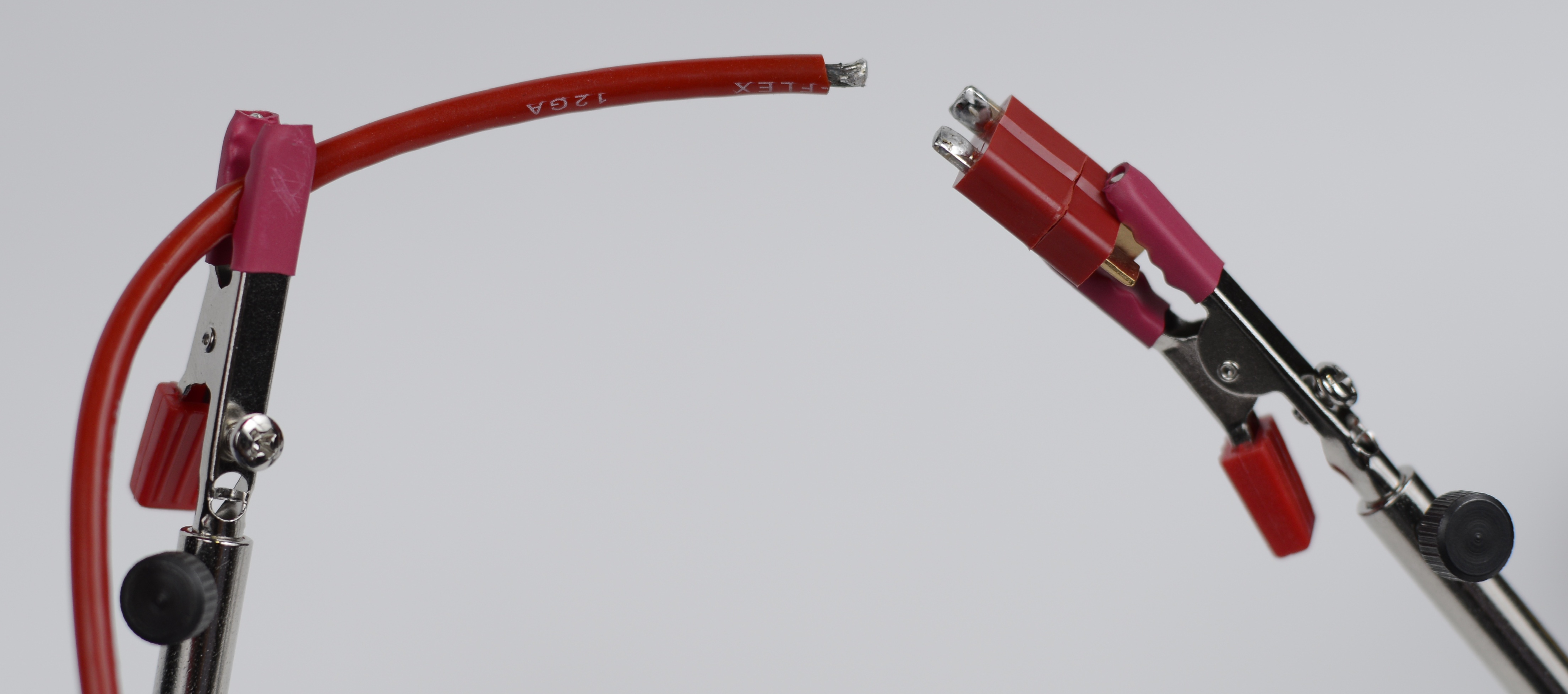
- Tinning the connections
This step will greatly simplify difficult soldering tasks such as power connections. Tin all of the separate connections to be joined by applying the soldering iron on the connection and pushing a thin layer of solder onto it. It is a good idea to secure the connection (see figure below) and apply flux to the connection (see step 3) before tinning. An example of a tinned wire and contacts are shown in the figure below.
 Fig. FA2.1 – tinning example
- (optional, highly recommended) Fluxing the connections
If a budget soldering iron is used, flux is its favorite companion. Even with a high power soldering iron, flux will make any soldering job easier. What it essential does is make solder flow better and near guarantees a good electrical joint. It also increases thermal contact between the connections and the iron. To use flux, apply a thin coat of the liquid substance to the soldering surfaces. Flux comes in various mediums of dispersion, such as a bottle, can or pen. A pen is arguably the most convenient. In the end, as long as the flux is coated onto the surfaces, its dispersion method is insignificant.
- Securing the connections
This is a very important step in soldering. A common mistake is to rush through this step to quickly jump into soldering. When this is conducted, chances are the unsecured connections move during soldering and the entire procedure has to be repeated, wasting additional time. Instead, patiently and firmly secure all of the connections to be soldered with third hands, vices, clamps, tape or any other feasible methods. The surfaces to be soldered should contact each other with sufficient force to resist movement during soldering. Well secured connections also prevent the connections from moving during the cool down process, satisfying the second criteria necessary to create a good electrical joint. In conclusion, doing this step properly goes a long way for the rest of the process. An example of a well secured platform ready for soldering is shown in the figure below. Fig. FA2.2 – secured connections example

- Tinning the tip
A tinned tip provides maximum heat transfer between the soldering iron and soldering surfaces. First clean the tip by swiveling it in a sponge or using a tip cleaner tool. Then, tin the tip by swiveling it in tip tinner or applying a small amount of solder around the tip. Clean off the excess material on the tip with a sponge or a tip cleaner tool. Once this is done, the tip should be nice and shiny, ready for soldering. Quickly proceed to soldering afterwards or the tip tinning process will have to be repeated.
- Soldering
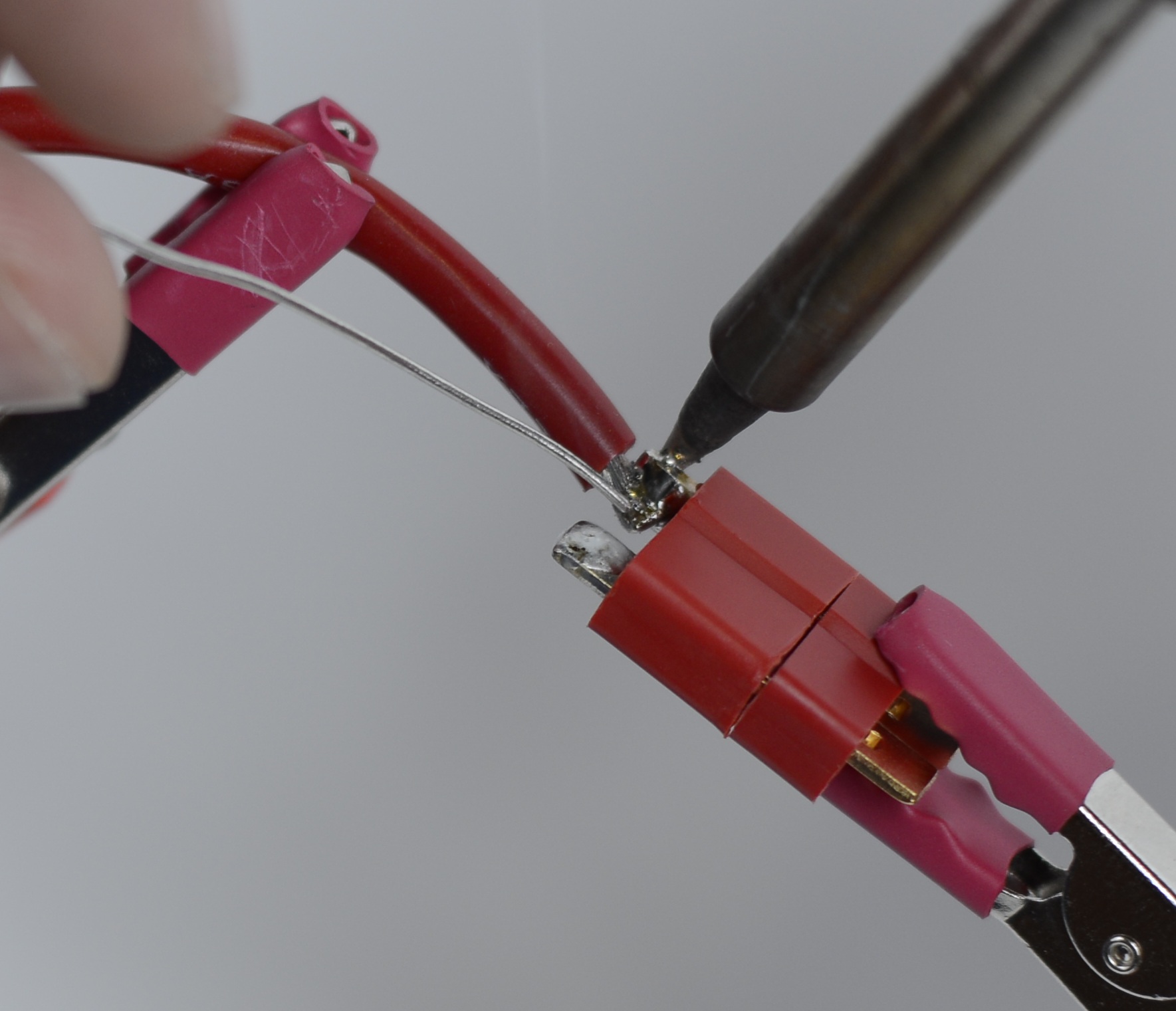
To effectively solder a joint, maximum heat transfer from the soldering iron to the connection surfaces is desired. To do this, apply the soldering iron to an area on the surface that will form the most contact with the tip. A common mistake is to use the tip of the iron tip (pointy part of the tip) to transfer heat. Although convenient, the very tip of the soldering iron is the least efficient way to transfer heat. Instead, use the sidewalls of the iron tip to solder. In addition, applying solder to the sidewalls of the tip after the iron contacts the desired connection surfaces is another way to increase heat transfer. Doing this increases the contact area between the iron and connection surfaces, allowing a higher rate of heat conduction. Although this method can be used to shorten the heating process, it is incorrect to solder by flowing solder through the tip. Flowing solder through the tip should only be used initially to increase surface contact between the tip and connection surfaces, it should not be the final step of soldering. Once solder is applied to the iron tip, it can be directly transferred and applied to the hot joint by simply relocating the solder feed from the iron tip to the joint. It is crucial for the final solder feed process to not touch the iron tip. Once the solder is able to be easily fed into the joint, the joint is hot enough to melt the solder and the proper temperature is reached. Keep applying solder until a layer covers all of the connection surfaces in the joint, but not so much that it creates a bubble of solder on the joint. A closeup of a final solder feed example is shown below.
 Fig. FA2.3 – soldering exampleNote that in this example, the soldering iron is applied to the backside of the connections joint. The soldering iron can be applied anywhere that allows for good heat transfer. It is a good idea to separate where the solder is being fed into the joint and where the soldering iron is applied (shown above) to ensure that the entire joint reaches the melting point of the solder.
- Lifting the soldering iron
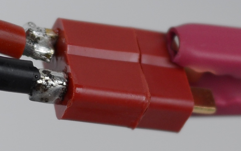
Once the desired amount of solder is applied, stop the solder feed and lift the iron from the joint. Do not lift the iron too fast or too slow, as doing so may cause undesired solder movement. The iron should be lifted in a quick manner; too slow will cause the solder to stick onto the iron during the lift and too fast may do the some thing with a sharp solder trail. If the solder keeps sticking to the join after a few attempts, apply some flux to the joint to easily prevent the problem. When soldering leads that will be cut after the solder such as through-hole components, it is a good idea to lift the soldering iron by dragging along the excess lead. This way, any trailing solder will stick to the excess lead, which will eventually be trimmed. As soon as the iron is lifted, be sure that none of the connections move during the cool-down process. If it does, a cold joint that may exhibit unpredictable electrical characteristics is created. This is why securing the connections from the beginning is crucial, as properly doing so will ensure the connections to not move during cool-down. In addition, do not blow on the joint to speedup the cooling process. This is a common mistake done by many. It may trap air pockets under the solder surface and create a cold joint. An example of well soldered joints is shown below. Fig. FA2.4 – finished joints exampleNote, the black burn marks are residual flux from soldering. It can be cleaned with water or acetone or whatever the flux used is soluble with.
- Inspection
In general, a shiny joint surface indicates that the electrical connection is good while a jagged joint surface means it is bad. With leaded solder, it is easy to tell whether a joint is good or not, as a shiny joint will always imply a good joint while a dull one will certainly indicate a bad one. However, with lead-free solder, it is harder to tell because a dull joint surface could mean a good or bad joint. The only way to distinguish the two is to be sure that the joint reached the melting temperature of the solder during soldering and that the joint did not move during the cool down process. Confirmation of these two conditions will guarantee a good electrical connection.
Following
the steps outlined above will ensure a proper soldering technique.
With enough practice, soldering will become a simple process. Here
are a few addition tips that may be useful:
- Use lead-free solder for high temperature applications, such as motor and power leads
- Use big tips for soldering large joints. Most soldering irons come with needle tips for soldering small connections. Replace them with bigger tips to easily and efficiently solder large joints.
- Always remember to put in heat shrink before soldering when necessary!
- Be aware of the soldering iron and its surroundings, the iron can unintentionally melt materials as well as cause injuries.
- Remain calm and do not get frustrated. Do not skip any steps when soldering, as it will often take more time to correct the mistakes caused by them. Do things right from the beginning to ensure a quick and easy job.
Regarding
the first tip, it is extremely important to use lead-free solder for
high temperature as well as potential high temperature applications.
The melting point of most leaded solder is 361 °F,
while 441 °F is the
common melting point for lead-free solder. Although most hobby
systems should never reach these temperatures, using lead-free solder
will ensure a reliable connection under extreme conditions.
In
terms of advanced soldering techniques, temperature setting of the
soldering iron is important. Different chemical compositions of
solder have unique melting properties. Some have a melting range,
where the temperature at which the solder melts varies greatly and/or
may gradually melt over a temperature range. Others have a defined
melting point, where the solder instantly transforms from a solid to
a liquid at a certain temperature. There may also be maximum
temperature restrictions, where the solder cannot form a good
electrical connection when soldered above a certain temperature. All
of these attributes can be found within the solder's
description/datasheet. One thing to keep in mind is that the solder
iron's temperature setting does not equate to the soldering
joint's temperature. Heat transfer occurs over time. A greater
temperature difference between two objects (iron and joint) means
faster heat transfer during contact, allowing for faster soldering. A
solder with a maximum temperature limit does not mean the soldering
iron used to solder it cannot be set above that limit. If the iron is
applied briefly to the joint, the joint will not reach the iron's
temperature and it will be within the maximum temperate limit of the
solder. If the solder is sensitive to its upper temperature limit,
the iron temperature should not be set far above the specification.
It is recommended that beginners use a relatively low iron
temperature setting and gradually increase it over experience until a
favorable setting is acquired. In general, do not set the iron
temperature above 850 °F.
It is also good practice to never apply the soldering iron for more
than a few seconds after the joint reaches the melting point of the
solder (a few seconds after the solder is easily feed-able).
A
few recommended soldering supplies are listed below:
- Lead-free solder (99.3% Tin, 0.7% Copper; for high temperature applications)
-MG chemicals 4901 Sn99: amazon - Leaded solder (63% Tin, 37% Lead; for low temperature applications)
-MG Chemicals 4880 Series: amazon - Tip cleaner
-Hakko Tip Cleaner 599B-02: amazon - Water soluble flux
-SRA #80 Water Soluble Soldering Flux Pen: amazon - Tip tinner
-MG Chemicals 4901 SAC305: amazon - Solder Sucker/Desoldering pump
-Paladin Tools 1700 Desoldering Tool: amazon - Desoldering braid
-Chemtronics 10-5L: mouser
The
motor break-in process is very important. Not only does it increase
motor life, it also significantly increases motor performance. For a
brushed DC motor, the break-in process transforms the brushes,
bushing or bearings and other moving/sliding parts from their new,
out of the factory state to their normal operating state. Ideally,
the break-in process for this type of electric motor starts by
applying a voltage above the no load stall voltage, then slowly
increasing the motor speed with intervals of voltage bursts. This
process would require a motor driver, which is quite inconvenient.
Since a flywheel system requires two motors, an easy way to break-in
the motors is by connecting them in series to the battery (as oppose
to parallel, which is normally how they are connected for maximum
power). This will run the motors at approximately half of their final
running speeds, assuming the same battery is used that will power the
finished system. If the motors are slightly, or even significantly
out of balance with respect to each other, it should not be a problem
since all this will do is make one motor run somewhat faster than the
other during the break-in process. As long as the motors do not have
load on them and are below the advertised maximum operating voltage,
it should not be a concern. One thing to note is to remove the
decoupling capacitors on the motors (most aftermarket motors such as
all Tamiya Mini series motors and RM2s do not have them, the PNs do)
before performing this process, as the capacitors will randomly
change the impedance of the motors from the brushes noise and make
the load on the motors unbalanced. The schematic for the electrical
connection of this break-in process is shown below.

Fig. FA3.1
– serial motors break-in process schematic
One thing to double check is the orientation of the battery connections to ensure that the flywheels spin the right way. A picture of the actual system is shown below.

Fig.
FA3.2 – actual break-in process picture
Note that the motors are already
placed in the flywheel cage. This is convenient because the motors do
not have to be secured, but the flywheel cage does (tape it down to a
surface with electrical tape). Also note that the positive connection
has not been applied to the motors yet in the picture to avoid
running the motors while taking the picture. Lastly, just because
connecting the motors in series works for this process does not mean
it can be used for the final build as a way of halving the voltage
across the motors. Ideally, this will work in the perfect world. But
in this world with its infinite random variables, a set voltage must
be applied across the motors by connecting them in parallel with the
battery.


All
current (mid 2013) Nerf flywheel blasters use 130-sized motors with a
25 mm length (there are 130-sized motors that are longer). A popular
replacement for these stock motors is the Solarbotics RM2 motors.
Additional alternatives include all of the Tamiya Mini series motors.
Although the Tamiyas run at considerably lower voltage (3V) comparing
to the RM2s, their ultra high Kv more than makes up for it. Tamiyas
are to a Ferrari as the RM2s are to a Lamborghini. One is finely
engineered while the other is purely brutal. At this point, choosing
between the two types is mostly based on preference. In terms of the
performance, a range test was conducted between the two motors and
the results are inconclusive. Once the chronometer is built
(currently under construction), a comparison will be made again and
the results will be posted. The Tamiyas might be a bit more
expensive, but there are also built with higher quality, making them
more reliable and consistent. Battery availability should also be
considered when choosing between the motors.
Although
the motors can be chosen indifferently, the batteries cannot. The
motor and battery combination must be carefully matched to optimize
the system. Since there are various types and vast numbers of
different batteries out there, but only a few choices of motors, it
is easier to first select the motor as the limiting factor, and then
match the battery to the selected motor. For the most part, there are
only two key specifications of a battery that needs to be considered:
output voltage and maximum burst current. In terms of the output
voltage, simply match it to, or slightly higher above (over-volting),
the specified maximum operating voltage of the motor. There is a
small tricky part to this step. The advertised voltage of a battery
is usually not the voltage it outputs at full charge. For example,
the advertised voltage of a rechargeable NiMH AA battery may be 1.2
V, but it can output as high as 1.46 V when charged. Similarly, the
advertised voltage for a LiPo cell is 3.7 V, but it outputs 4.2 V
when charged. The reason for this is because the advertised voltage
is usually the nominal, storage and/or some other defined voltage
parameter of the battery. However, this does not mean that it is
their highest capable output voltage. Another important parameter to
consider is the output voltage of the battery as a function of time
during use. Normal Alkaline batteries' voltage decreases linearly
with time. NiMH rechargeable batteries' voltage decreases in an
inverse exponential form, allowing them to maintain their maximum
output voltage for longer.

Fig. FB1.1
– voltage vs. time comparison
Although it is encouraged to
develop a system based on preference, please make sure to choose
parts that match the desired specifications to create a high
performance, durable system.
A common modification conducted
by the Nerf community is to use unprotected TrustFire 14500 batteries
in their systems. Although this modification is simple, clean and
cheap, engineering-wise, it is a terrible design and highly not
recommended. The TrustFire 14500 has a maximum continuous discharge
current of 2.5 C, which means that the maximum burst output current
is approximately 4.5 A. The stall current of a RM2 motor at 12.6 V is
around 12.42 A (probably around 6.21 A for a flywheel system). With
two RM2 motors for a flywheel system, the required burst current is
24.84 A (or 12.42 A for a flywheel system), which is no where near
what the TrustFire batteries are capable of producing. Evidence of
this can be physically observed by the slow speedup time of a
RM2-TrustFire system. Currently, LiPo batteries are the best type of
batteries to use in a hobby-level, high power electrical system. The
new generation of LiPo batteries are very safe and reliable, provided
that they are used correctly. They are capable of producing immense
power, able to contain high capacity, relatively light, widely
available and cheap. They also have a high number of recharge cycles
for its lifetime. The downsides for using LiPo batteries are that it
requires a special charger which costs around $40, and also it may be
dangerous when handled by a novice. To create the best system
possible, LiPo batteries are an absolute necessity because of their
low internal resistance. If moderate modifications are desired, other
battery types will do the job so long as the specifications are met.
Instead of using TrustFire batteries, RC-grade NiMH packs are a good
alternative. They are usually rated for anywhere from 10 to 20 A of
continuous current and are extremely safe, with almost no possibility
of catching fire in any condition.
Below are a few useful battery
equations:
Equation
FB1.1 – continuous current equation
Note, Cn is the
normalization constant for the discharge rate calculation.
Specifications for a battery usually lists Icont as the
following:
Discharge rate: 25C
This implies that the continues
discharge rate (Icont) is equal to 25 times the capacity
of the battery in Ah. In this case, 25 is the Cn. Icont
should be greater than the continuous current of the motor(s) under
light load (powering flywheels).
Equation
FB1.2 – max current approximation
This approximation is valid for
most types of batteries such as LiPo batteries. Imax
should be greater than the stall current of the motor(s).
Equation
FB1.3 – battery run time approximation in minutes
A few good sources for motor and
battery purchase are listed below:
- Hobbylinc: http://www.hobbylinc.com/
Comments: Stocks almost every Tamiya Mini series motors with a good discount. Fast shipping and handling (~1 week package arrival). - TamiyaUSA: http://www.tamiyausa.com/
Comments: MSRP pricing on Tamiya motors, but good stock availability (in case Hobbylinc is out). Medium shipping and handling speed (<3 weeks package arrival) - Pololu: http://www.pololu.com/
Comments: Good source for RM2s and other industrial-type 130-sized motors. Fast shipping and handling (~1 week package arrival). - Tower Hobbies: http://www.towerhobbies.com/
Comments: Great source for many RC batteries. Also stocks some Tamiya motors. Handling is fast but the value shipping method is slow (~2 weeks package arrival with value shipping). - Hobbypartz: http://www.hobbypartz.com/
Comments: Huge selection of high quality as well as cheap LiPo batteries (high quality Chinese LiPos). Availability is somewhat low (they sell out really fast after receiving stock). Good source for a LiPo charger as well. Fast shipping and handling (~1 week package arrival). - Hobbyking: http://www.hobbyking.com/hobbyking/store/index.asp
Comments: Huge selection and availability of RC batteries including decent quality LiPos (average quality Chinese LiPos). Shipping and handling is fast for the USA warehouse products (<2 weeks package arrival), slow for the international warehouse products (3 weeks to 2 months package arrival).
ICE BREAKER
ReplyDeleteSuperb mod guide and pictures, thank you!
ReplyDeleteYour appreciation is greatly appreciated :DD
Deleteinstead of using relays, can I use an SPDT micro switch? (link below)
ReplyDeletehttp://www.ebay.com/itm/290723653962?ssPageName=STRK:MEWNX:IT&_trksid=p3984.m1439.l2649
normally close will be connected to battery negative so that when the acceleration trigger is released, 2 negatives will go the the flywheel motors.
please advise if this achieves the same goal as the relay diagram posted.
Yes, a SPDT should be fine, that one looks like it is rated for enough current too.
DeleteLet us know how it goes!
additional details:
ReplyDeletecommon will go to motor (+)
NC go to battery (-)
NO go to battery (+)
real badass modder.. really appreciate your time to make this blog. Good job! really love the way you mod. if only there's the shooting comparisson video :(
ReplyDeleteDownload New Real Racing 3 2015 Hacks Free Working Here:
ReplyDeletehttp://dlhack.com/download/real-racing-3-hacks
http://dlhack.com/download/real-racing-3-hacks
http://dlhack.com/download/real-racing-3-hacks
http://dlhack.com/download/real-racing-3-hacks
http://dlhack.com/download/real-racing-3-hacks
http://dlhack.com/download/real-racing-3-hacks
http://dlhack.com/download/real-racing-3-hacks
http://dlhack.com/download/real-racing-3-hacks
http://dlhack.com/download/real-racing-3-hacks
http://dlhack.com/download/real-racing-3-hacks
http://dlhack.com/download/real-racing-3-hacks
Watch WRC Mexico Rally 2016 Online Live on your smartphone,
ReplyDeleteon your computer or tablet..
Stream 1 : www.watchwrconline.com
Stream Link : www.watchwrconline.com
I am so pleased to have found the site that can be useful for me and that is really good to have found the site liek that http://custom-paper-writing.com/blog/essay-editing-service my husband will be pleased.
ReplyDelete